Author: Sam

  • 2015 Touring – TURN SIGNAL LAMPS – TURN SIGNAL BULB REPLACEMENT: FLAT LENS STYLE

    1. See Figure 7-36. Remove two screws to release lens from lamp housing.

    2. Push bulb in and rotate counterclockwise to remove bulb from socket.

    3. Inspect condition of electrical contacts in socket. If necessary, clean with a small wire brush and electrical contact cleaner.

    4. Apply ELECTRICAL CONTACT LUBRICANT to contacts in socket and at bottom of new bulb.

    5. Align index pins on new bulb with pin guides in bulb socket. Push bulb in and turn clockwise to lock in place.

    6. Seat lens in lamp and install two screws.

    Be sure that all lights and switches operate properly before operating motorcycle. Low visibility of rider can result in death or serious injury. (00316a)

    7. Test lamp operation.


  • 2015 Touring – TURN SIGNAL LAMPS – TURN SIGNAL BULB REPLACEMENT: BULLET STYLE

    1. See Figure 7-35. Insert a coin or the blade of a small screwdriver into the notch at the bottom of the lens cap.
    Carefully twist until the lens cap pops out of the lamp housing.

    2. Push bulb in and rotate counterclockwise. Pull bulb from socket.

    3. Inspect condition of electrical contacts in socket. If necessary, clean with a small wire brush and electrical contact cleaner.

    4. Apply ELECTRICAL CONTACT LUBRICANT to contacts in socket and at bottom of new bulb.

    5. Align pins on new bulb with pin guides in bulb socket.
    Push bulb in and turn clockwise to lock in place.

    6. Snap lens cap onto the lamp housing with notch at bottom.

    7. Test lamp operation.


  • 2015 Touring – TOUR-PAK LIGHTS – WRAP-AROUND LAMP (IF EQUIPPED)

    Removal

    1. Remove Tour-Pak liner. See 2.34 TOUR-PAK SERVICE, Tour-Pak Liner.

    2. Remove both antenna masts from lamp housing.

    3. See Figure 7-34. Disconnect radio antenna cable connector (3).

    4. Disconnect electrical connector (4).

    5. Disconnect CB antenna cable connector if equipped.

    6. Remove nut (5), washer and ring terminal from CB antenna stud.

    7. Remove nut (2), ring terminal and large flat washer from AM/FM radio antenna stud.

    8. Remove eight screws (1) to free lamp assembly from TourPak.

    Repair

    1. Remove CB antenna stud and remove antenna base from lamp housing.

    2. Using the original nut and a 1/2 in.-20 UNF nut as a jamnut, remove connector stud from radio antenna base.

    3. Remove inner stud. Remove antenna base from lamp housing.

    4. Install radio antenna base with inner set screw. Tighten to 14-16 in-lbs (1.6-1.8 Nm).

    5. Install radio antenna connector stud. Tighten securely.
    Remove nuts.

    6. If equipped, install CB antenna base into lamp housing and secure with set screw. Tighten to 14-16 in-lbs (1.6-1.8 Nm).

    Installation

    1. See Figure 7-34. Install lamp and secure with eight screws (1). Tighten to 20-25 in-lbs (2.3-2.8 Nm).

    2. Install electrical connector (4).

    3. Install large flat washer, ring terminal and nut (2) onto AM/FM radio antenna stud. Tighten to 16-19 in-lbs (1.8-2.1 Nm).

    4. Connect AM/FM radio antenna cable connector (3).

    5. Install ring terminal, flat washer and nut (5) onto CB antenna stud. Tighten to 14-16 in-lbs (1.6-1.8 Nm). Connect CB antenna cable if equipped.

    6. Install both antenna masts.

    7. Install Tour-Pak liner. See 2.34 TOUR-PAK SERVICE, Tour-Pak Liner.

  • 2015 Touring – TOUR-PAK LIGHTS – TOUR-PAK LIGHTS HARNESS

    Removal

    1. Remove Tour-Pak liner. See 2.34 TOUR-PAK SERVICE, Tour-Pak Liner.

    2. Remove Tour-Pak. See 2.33 TOUR-PAK.

    3. See Figure 7-33. Remove radio antenna cable (7).

    4. Remove nut and ring terminal securing CB antenna cable (8).

    5. Remove four screws (3) securing ground plate. Disconnect two ground connectors. Remove ground plate.

    6. Disconnect side marker lamp connectors (4, 6).

    7. Disconnect power outlet connector (2).

    8. Push grommet with harness out toward front. Remove Tour-Pak lights harness.

    Installation

    1. See Figure 7-33. Install rubber grommet on harness with the split down. Position next to cable strap (1).

    2. Route Tour-Pak lights harness through hole into Tour-Pak.
    Install grommet.

    3. Place harness at bottom of Tour-Pak.

    4. Mate marker lamp (4, 6) and power outlet (1) connectors.

    5. Install ground plate with four screws (3). Tighten to 20-25 in-lbs (2.3-2.8 Nm).

    6. Connect audio radio antenna cable (7).

    7. Install CB antenna cable (8), flat washer and nut onto stud.
    Tighten to 14-16 in-lbs (1.6-1.8 Nm).

    8. Install Tour-Pak. See 2.33 TOUR-PAK.

    9. Install Tour-Pak liner. See 2.34 TOUR-PAK SERVICE, Tour-Pak Liner.


  • 2015 Touring – TOUR-PAK LIGHTS – TOUR-PAK SIDE LAMPS/TRIM STRIPS

    Removal

    NOTE

    The Tour-Pak may be equipped with either side marker lamps or trim strips depending on model. Removal and installation are similar.

    1. Remove Tour-Pak liner. See 2.34 TOUR-PAK SERVICE, Tour-Pak Liner.

    2. Remove Tour-Pak. See 2.33 TOUR-PAK.

    NOTE

    See Figure 7-33. Screws (3) secure both the ground plate and marker lamp/trim strip.

    3. See Figure 7-33. Remove four screws (3) securing ground plate. Disconnect two ground connectors. Remove ground plate.

    4. Lamp equipped:
    a. Disconnect side marker lamp connector (4 or 6).
    b. Remove split bushing. Pull harness and connector through hole.

    Installation

    1. Lamp equipped:
    a. See Figure 7-33. Feed connector through hole in Tour-Pak and place side marker lamp into position.
    b. Install split bushing.
    c. Connect side marker lamp connector (4 or 6).

    2. Install ground plate with four screws (3). While holding lamps or trim strips in position, tighten to 20-25 in-lbs (2.3-2.8 Nm).

    3. Mate two ground connectors to ground plate.

    4. Install Tour-Pak. See 2.33 TOUR-PAK.

    5. Install Tour-Pak liner. See 2.34 TOUR-PAK SERVICE, Tour-Pak Liner.


  • 2015 Touring – FENDER TIP LAMPS – REAR FENDER TIP LAMP

    Removal

    1. Remove and disconnect tail lamp assembly from chrome base.

    2. See Figure 7-31. Disconnect rear fender tip lamp connector [45] (2).

    3. Remove harness from upper clip on inner side of fender.

    4. Remove locknut, washer and P-clamp securing harness near lamp.

    5. See Figure 7-32. Remove two screws (2).

    6. Remove fender tip lamp.

    Installation

    1. See Figure 7-31. Route rear fender tip lamp harness through hole at bottom of fender and back through opening (3). Attach rear fender tip lamp connector [45] (2).

    2. Secure lamp harness to upper clip on inner side of fender.

    3. Secure lower portion of harness with P-clamp, washer and locknut. Tighten to 45-85 in-lbs (5.1-9.6 Nm).

    4. See Figure 7-32. Place fender tip lamp into position. Secure with two screws (2). Tighten to 12-18 in-lbs (1.4-2.0 Nm).

    5. See Figure 7-31. Attach tail lamp connector [93] (1).

    6. Install tail lamp with two screws. Tighten to 20-24 in-lbs (2.3-2.7 Nm).

    Be sure that all lights and switches operate properly before operating motorcycle. Low visibility of rider can result in death or serious injury. (00316a)

    7. Test lamp operation.


  • 2015 Touring – FENDER TIP LAMPS – FRONT FENDER TIP LAMP

    Removal

    1. Remove outer fairing and front fender. See 2.48 FRONT FENDER.

    2. See Figure 7-29. Remove nuts (2) securing left fender trim strip. Remove trim strip.

    3. Remove nuts (3) securing fender tip lamp. Remove lamp and harness assembly.

    Installation

    NOTE

    Over-tightening screws can crack the bracket or scratch the fender paint.

    1. See Figure 7-29. Mount fender tip lamp. Secure with nuts (3). Tighten to 20-25 in-lbs (2.3-2.8 Nm).

    2. See Figure 7-30. Route harness through trim strip and into oblong hole (5). Confirm harness routes between trim strip and tee bolt.

    3. Secure trim strip with two nuts. Tighten to 10-15 in-lbs (1.1-1.7 Nm).

    4. See Figure 7-29. Route harness between fender and fender mounting bracket (1).

    5. Route harness out through grommet and install connector housing.

    6. Install fender and outer fairing. See 2.48 FRONT FENDER.

    Be sure that all lights and switches operate properly before operating motorcycle. Low visibility of rider can result in death or serious injury. (00316a)

    7. Test lamp for proper operation.


  • 2015 Touring – REAR LIGHTING – REAR FENDER LIGHTS HARNESS: FLHX/S, FLTRX/S

    Removal

    1. Remove left saddlebag and left side cover.

    2. See Figure 7-26. Cut cable strap (3).

    3. Separate connector (2).

    4. See Figure 7-27. Release harness from upper clips (1).

    5. Release harness from molded clips (2) on fascia.

    6. Disconnect harness from fender tip lamp.

    7. Note harness routing. Remove harness.

    NOTE

    Canadian models have both a turn signal light bar and tail lamp, and include an extra jumper harness.

    8. Canadian Models: See Figure 7-28.
    a. Remove rear fender. See 2.49 REAR FENDER.
    b. Remove tail lamp lens.
    c. Disconnect jumper harness (2) from the rear fascia lamp and the tail lamp.
    d. Release jumper harness from clamps (1, 3) and remove from fender.

    Installation

    1. Canadian Models: See Figure 7-28.
    a. Route jumper harness (2) from tail lamp to the fascia lamp and connect to each lamp.

    NOTE

    Do not over-tighten screws.

    b. Install tail lamp lens and tighten screws to 20-24 in-lbs (2.3-2.7 Nm).
    c. Secure jumper harness with clamps (1, 3). Install fender. See 2.49 REAR FENDER.

    2. See Figure 7-26 and Figure 7-27. Route harness in approximate position, passing back under frame cross member and through opening in left caddy.

    3. See Figure 7-27. Pass harness over antenna mount (3). Secure harness in molded clips (2) on inside of fascia.
    Connect to fender tip lamp. Pull harness up to remove slack near fender tip lamp.

    4. Secure harness in three upper clips (1).

    5. See Figure 7-26. Pull slack from harness. Secure rear lighting harness and antenna cable to left upper frame with new cable strap (3).

    6. Mate connector (2). Secure connector housing to upper caddy.

    7. Install side cover and saddlebag.

    Be sure that all lights and switches operate properly before operating motorcycle. Low visibility of rider can result in death or serious injury. (00316a)

    8. Check operation of all lamps.


  • 2015 Touring – REAR LIGHTING – REAR FASCIA LAMP

    Removal

    1. See Figure 7-25. Remove shield (7) and disconnect rear lights harness and tail light jumper harness from fascia lamp.

    2. Remove screws securing lamp (8).

    Installation

    1. See Figure 7-25. Secure lamp (8) with two screws. Tighten to 18-22 in-lbs (2.0-2.5 Nm).

    2. Connect rear lights harness and tail lamp jumper harness to fascia lamp.

    3. Install shield (7).


  • 2015 Touring – REAR LIGHTING – REAR FENDER LIGHTS HARNESS: ALL EXCEPT FLHX/S, FLTRX/S

    Removal

    NOTE

    FLHTC models use a jumper harness between the fender harness connector and the main harness connector located in the left electrical caddy. That harness can be removed and installed independent of the fender harness.

    1. Remove rear fender. See 2.49 REAR FENDER.

    2. Remove and disconnect tail lamp assembly from chrome base.

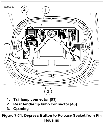
    3. See Figure 7-20. Disconnect connector (5). Feed through opening to inboard side of fender.

    4. See Figure 7-23. Release turn signal lamp wires from cable clips (3). On FLHTCU, FLHTK models, release wire from stamped fender clip (4).

    5. FLHTCU, FLHTK models: Release wire from stamped fender clip (4).

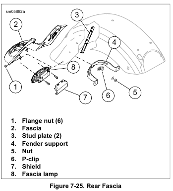
    6. Release harness from channel in stud plate (2). Loosen flange nuts if necessary.

    7. Remove adhesive conduit (1) with wire harness from fender well.

    8. If replacing only conduit (1):
    a. Carefully cut adhesive conduit. Remove wire harness.
    b. Remove rear connector from harness. See B.1 CONNECTORS.

    Installation

    1. Clean fender:
    a. Thoroughly clean fender well with soap and water. Do not use solvents or harsh chemicals that may damage painted surfaces.
    b. Remove all residual adhesive using 3M GENERAL PURPOSE ADHESIVE REMOVER.
    c. See Figure 7-23. Using a soapy non-abrasive scouring pad, thoroughly clean fender well in area of adhesive conduit.
    d. Rinse with clear water and thoroughly dry with a clean white cloth. Repeat until clean cloth shows no evidence of dirt.
    e. Swab area with isopropyl alcohol. Allow to dry.

    2. If replacing only the adhesive conduit:
    a. See Figure 7-24. Verify cable strap (3) is installed as shown to prevent rearward movement of the harness.
    b. Draw harness through new conduit until progress is halted by installed cable strap (3).

    3. Install connector housing on harness. See B.1 CONNECTORS. Refer to Table 7-8.

    4. See Figure 7-23. Remove paper backing and lightly press conduit in location shown in graphic.

    5. Use a wallpaper seam roller to press conduit securely in place.

    6. Allow the adhesive 72 hours to fully cure. Installation of the fender may proceed, but exercise caution to avoid pulling or repositioning adhesive conduit.

    7. Feed forward connector housing of harness through hole in front of fender.

    8. Capture harness in channel of stud plate (2). If loosened, tighten flange nuts to 60-96 in-lbs (6.8-10.9 Nm).

    9. Feed rear harness connectors through openings in fender and capture turn signal lamp wires in cable clips (3).

    10. FLHTC/U, FLHTK models: Capture rear fender tip lamp wire in stamped fender clip (4).

    11. See Figure 7-20. Mate tail lamp connectors (3, 4) to tail lamp base.

    12. Verify that tail lamp harnesses are routed as shown in Figure 7-19.

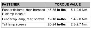
    13. Install tail lamp. Tighten to 20-24 in-lbs (2.3-2.7 Nm).

    14. Install rear fender. See 2.49 REAR FENDER.

    Be sure that all lights and switches operate properly before operating motorcycle. Low visibility of rider can result in death or serious injury. (00316a)

    15. Test tail lamp operation.