Disassembly
1. Remove end cover, if equipped.
2. Remove two nuts to release end cover bracket from through bolts, if equipped.
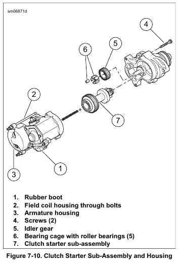
3. See Figure 7-10. Pull up rubber boot (1). Remove hex nut with captive lockwasher. Release field wire from terminal post on solenoid housing.
4. Loosen two through bolts (2) to release field coil housing from solenoid housing.
NOTE
Do not remove armature and brush plate from housing. No replacement parts are available.
5. Remove armature housing (3) keeping all contents together for reassembly.
6. Remove two screws to release drive housing from solenoid housing. Use a rubber mallet to separate drive and solenoid housings, if necessary.
7. Remove idler gear (5) from bearing cage in drive housing.
Remove bearing cage with five roller bearings (6) from shaft in drive housing.
8. Push on end of drive shaft to remove clutch starter sub assembly (7) from drive housing.
9. Remove solenoid spring and ball from the output shaft of the clutch starter sub assembly.
Inspection
1. Inspect two O-rings on drive housing for damage. Replace if necessary.
2. See Figure 7-10. Verify that the idler gear (5) rotates freely without drag or sticking.
3. Remove and inspect idler gear. Replace starter motor if the gear is damaged.
4. Inspect roller bearings (6). Bearings must rotate freely without drag or sticking. Replace starter motor if the bearings are pitted or grooved.
5. Inspect the steel ball for damage. Replace if necessary.
NOTE
Replace entire starter motor if solenoid return spring fails.
Assembly
1. See Figure 7-10. Assemble starter.
a. Lubricate parts with high temperature grease such as LUBRIPLATE 110 during assembly.
b. Install bearing cage with five roller bearings (6) onto shaft in drive housing.
c. Confirm that all five roller bearings are installed in grooves of bearing cage and install idler gear (5) over bearing cage.
2. Lubricate bearings with LUBRIPLATE 110 before installation. Install new clutch starter sub assembly (7) in drive housing seating the larger bearing in the counterbore.
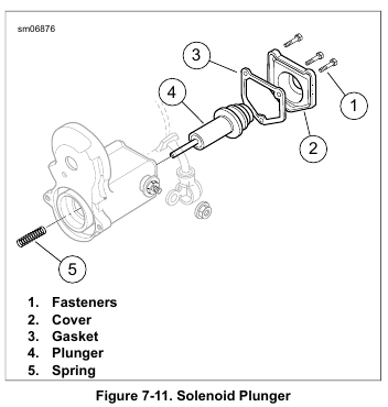
3. Apply a light film of LUBRIPLATE 110 to solenoid plunger shaft. Install return spring on solenoid plunger shaft.
NOTE
Before mating the solenoid and drive housings, apply a thin layer of HARLEY-DAVIDSON HIGH PERFORMANCE SEALANT – GRAY to drive housing between the two housings.
4. Mate the solenoid and drive housings with two screws.
Alternately tighten until snug.
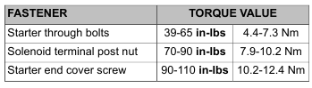
5. Install through bolts to fasten field coil to solenoid housing.
Tighten to 39-65 in-lbs (4.4-7.3 Nm).
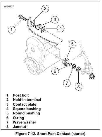
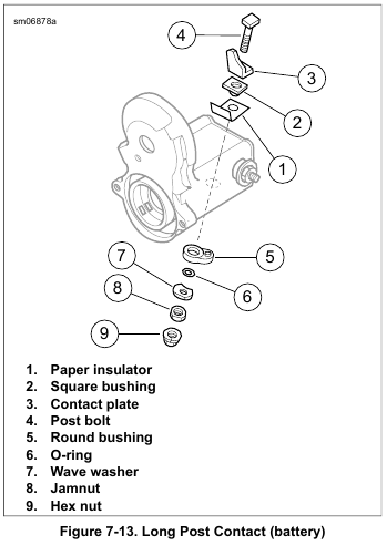
6. Secure field wire ring terminal to short post on solenoid housing with hex nut with captive lockwasher. Tighten to 70-90 in-lbs (7.9-10.2 Nm). Cover field wire ring terminal with rubber boot (1).
7. Install end cover bracket onto through bolts, if equipped. Orient longest end of bracket on the field wire side. Install two nuts. Tighten until snug.
8. Install end cover, if equipped. Tighten to 90-110 in-lbs (10.2-12.4 Nm).