Cover and Plunger Removal
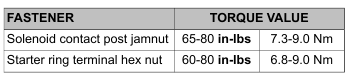
1. See Figure 7-11. Remove fasteners (1), cover (2) and gasket (3).
2. Remove the plunger (4) with spring (5).
Short Post Contact: Starter
1. Disassemble the short post contact:
a. Remove the hex nut and the ring terminal from the post.
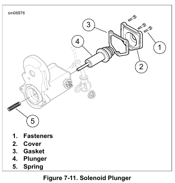
b. See Figure 7-12. Remove jamnut (8), wave washer (7), O-ring (6) and round bushing (5).
c. Remove the post bolt (1).
d. Remove the hold-in terminal (2) from the post bolt.
e. Remove the contact plate (3) and the square bushing (4).
2. Assemble the short post contact:
a. Insert the square bushing into the housing.
b. Install the contact plate with the 90 degree part of the contact plate against the solenoid winding.
c. Install the post bolt through the hold-in terminal, the contact plate and the square bushing.
d. Install the round bushing, O-ring, wave washer and jamnut.
Long Post Contact: Battery Positive
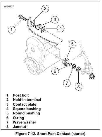
1. See Figure 7-13. Remove the long post contact:
a. Remove hex nut (9).
b. Remove jamnut (8), wave washer (7), O-ring (6) and the round bushing (5).
c. Remove post bolt (4), contact plate (3), square bushing (2) and paper insulator (1).
2. Install the long post contact:
a. Insert the square bushing through the paper insulator into the housing.
b. Install the contact plate with the foot against the solenoid winding.
c. Install the post bolt.
NOTE
Check that the index pin on the round bushing fits the blind hole in the housing.
d. Install the round bushing, O-ring, wave washer and jamnut.
Plunger and Cover Installation
1. Apply LUBRIPLATE 110 to the plunger shaft. Install the spring.
2. Install the plunger and spring in the housing.
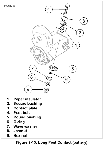
3. While compressing the plunger, alternately tighten the contact post jamnuts to 65-80 in-lbs (7.3-9.0 Nm).
4. Check that the contact plates are aligned to the solenoid winding.
5. Install the cover:
a. Install a new gasket on the cover.
b. Install the cover.
c. Install the fasteners until snug.
6. Install the starter positive ring terminal.
7. Install the hex nut. Tighten to 60-80 in-lbs (6.8-9.0 Nm).
Leave a Reply