Author: Sam

  • 2015 Touring – MAIN WIRING HARNESS – INSTALLATION: ALL MODELS (PART 1)

    1. Feed front end of wire trough in through opening between left frame downtubes, then pull up and out through opening at top of battery tray. Lay wire trough on top of frame backbone.

    2. Push anchor pins at rear of wire trough into holes in frame backbone.

    3. Locate the lower front branch terminating at the voltage regulator, stop lamp switch, oil pressure switch, and so forth. Route down inside of mid down tube and to front of motorcycle following the lower frame tube.

    4. Locate branch terminating in the VSS, neutral switch and starter solenoid connectors. Route down through opening right of ignition coil to top of transmission.

    5. Locate branch terminating in oxygen sensor, ABS module (if equipped) and rear wheel speed sensor connectors.
    Route down to area of right caddy.

    6. Models with Tour-Pak: Locate branch terminating in the Tour-Pak lights and audio harness connectors. Route along left upper frame tube to area near Tour-Pak. Mate connectors. Secure audio connector to anchor.

    7. Route starter power cable and ignition coil connector down through opening left of ignition coil.

    8. Route rear fender lights connector through opening at rear of battery tray and up through frame crossmember. Install left side electrical caddy. See 7.6 ELECTRICAL CADDIES.

    9. All except FLHX/S, FLTRX/S: Mate rear fender lights connector. Secure to top of fender.

    10. FLHX/S, FLTRX/S: Mate rear fender lights connector.
    Secure to top caddy.

    11. Install BCM. See 7.5 BODY CONTROL MODULE (BCM).

    12. Connect VSS and neutral switch.

    13. Install ignition coil connector [83].

    14. Install starter. See 7.8 STARTER.

    15. Install purge solenoid connector [95] if equipped.

    16. Install main harness ground ring terminals:
    a. Install two main harness ground ring terminals onto left frame ground stud. Secure with nut.
    b. Install remaining ground ring terminal on right frame ground stud under starter ground cable ring terminal.
    Secure with nut.
    c. Tighten both nuts (metric) to 50-90 in-lbs (5.7-10.2 Nm).

    NOTE

    Replace conduit clips if damaged, deteriorated or missing. With the slotted side up, push hole in conduit clip over T-stud to install.

    17. Route lower front branch inboard of front engine mounting bracket.

    18. Twin-Cooled: Route pump and fan connectors under the front engine mount.

    19. Connect and install voltage regulator. See 7.20 VOLTAGE REGULATOR.

    20. Connect CKP sensor connector [79]. Push anchor on connector into hole in front caddy.

    21. Connect jiffy stand interlock sensor connector [133].
    Secure to T-stud on front caddy.

    22. See Figure 7-120. Secure the regulator harness and jiffy stand sensor harness to the frame with a new cable strap.

    23. Connect oil pressure switch/sender connector.

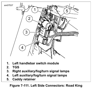
    24. See Figure 7-119. Connect brake lamp switch connectors:
    a. Support front of engine.
    b. Remove screws securing front right engine mount end cap.
    c. Carefully pull off end cap mount with footboard, master cylinder and brake pedal attached. Allow to lay beside the vehicle.
    d. Install stop lamp switch wire connectors (1).

    NOTE
    Confirm oil switch/sender wires are inboard of rubber mount.

    e. Install engine mount end cap. Tighten to 42-48 ft-lbs (56.9-65.0 Nm).

    25. Twin-Cooled: Mate pump, left fan and right fan connectors. Secure to anchors.

    26. Secure lower front branch to mid-frame down tube. See Figure 7-122 for location of new cable straps.

    27. Secure horizontal portion to conduit clips (4).

    28. Install connector [179] to the active exhaust valve actuator or to mock connector housing on right side of battery tray, as equipped.

    29. ABS equipped: Connect ABS module connector [166] and rear wheel speed sensor connector [168].

    30. Connect oxygen sensor front (gray) and rear (black) connectors. Secure connectors to anchors on right caddy.

    31. Secure harnesses to left upper frame tube with two new cable straps.

    32. FLHR/C Only:
    a. Lay a clean shop towel on forward part of rear fender.
    Lay console upside down on shop towel.
    b. Connect instrument console connector [20].
    c. Connect ignition switch jumper harness connector [222]. Secure connector in hole in left side of battery tray.

    33. Connect ECM connectors.

    NOTE

    ABS equipped: The order in which lines are arranged is important. Arrange as the insets show. See Figure 2-58.

    34. See Figure 2-58. Secure brake lines to wire trough including central anchor block.
    a. Secure lines at rear within retainer (4) and under the tab.
    b. Route lines under retainer tab (5).
    c. Secure lines in retaining features (6) at front of wire trough.
    d. See Figure 7-121. Install cable straps in locations shown to secure brake lines to wire trough.

    35. See Figure 7-117. Install connectors to induction module:
    a. Install TMAP sensor connector (3). Engage yellow lock.
    b. Install TCA connector (2). Install new anchored cable strap in hole at front right side of induction module.
    c. Install fuel injector connectors (1, 4).

    36. Mate ACR connectors. Secure to anchors.

    37. Install air cleaner assembly. See 4.5 AIR CLEANER ASSEMBLY.

    38. Route the branch to the horn and ET sensor to the left side of the engine and under the horn bracket. On Twin Cooled Models, route the branch under coolant lines.

    39. Connect ET sensor connector. Pull boot over sensor.

    40. Connect horn spade terminals. Capture conduit in J-clamp. Secure to horn bracket with anchored cable strap.

    NOTE

    Depending upon model, continue procedure at 7.35 MAIN WIRING HARNESS, Installation: Road King Models (Part 2), 7.35 MAIN WIRING HARNESS, Installation: Fork Mounted Fairing Models (Part 2).


  • 2015 Touring – MAIN WIRING HARNESS – REMOVAL: ALL MODELS (PART 3)

    1. Remove air cleaner cover and backplate. See 4.5 AIR CLEANER ASSEMBLY.

    2. Disconnect ACR connectors.

    3. See Figure 7-117. Remove connectors from induction module:
    a. Disconnect TMAP sensor connector (3). Pull back yellow lock, push down firmly on latch and disconnect connector.
    b. Disconnect fuel injector connectors (1, 4).
    c. Disconnect TCA connector (2). Release anchored cable strap securing harness to induction module.

    4. Disconnect terminals from horn and release harness conduit from J-clamp. Release anchored cable strap securing harness to horn bracket.

    5. Disconnect ET sensor connector [90].

    6. Draw harness branch to right side of motorcycle.

    7. ABS equipped: Release brake lines from wire trough.

    8. Cut cable straps securing harnesses to left upper frame rails.

    9. Disconnect purge solenoid connector [95], if equipped.

    10. Disconnect ECM connectors.

    11. Disconnect ignition coil connector [83].

    NOTE

    Record harness ground ring terminal orientation when removing.

    12. Remove main harness ground ring terminals from left and right frame ground studs (metric) located ahead of battery tray.

    13. Pry anchor pins at rear of wire trough from holes in frame backbone.

    14. Disconnect siren if equipped. Remove siren from left side caddy.

    15. Remove BCM. See 7.5 BODY CONTROL MODULE (BCM).

    16. Remove screws securing left side caddy. See 7.6 ELECTRICAL CADDIES.

    17. FLHR/C Only:
    a. Pull anchor on ignition switch jumper harness connector [222], 4-place Packard, from hole in left caddy.
    Disconnect connector.

    b. Disconnect instrument console connector [20], 16 place Molex, inboard of left upper frame tube. Remove instrument console.

    18. FLHX/S, FLTRX/S:
    a. See Figure 7-118. Disconnect radio antenna cable connector (1).
    b. Disconnect rear lighting connector (2).

    19. Models with Tour-Pak: Disconnect rear audio harness, antenna and Tour-Pak lighting connectors located near Tour-Pak. Release audio connector from anchor.

    20. Disconnect oxygen sensor connectors. Remove from anchors.

    21. Disconnect connector [179] from active exhaust valve actuator or from mock pin housing on right side of battery tray, as equipped.

    22. ABS models:
    a. Disconnect ABS module connector [166].
    b. Disconnect rear wheel speed sensor connector [168].

    23. Draw harness branch into battery tray.

    24. Remove main power cable ring terminal from starter solenoid post. Draw out cable through opening at rear of left side caddy.

    25. Remove starter and disconnect VSS connector. See 7.22 VEHICLE SPEED SENSOR (VSS).

    26. Remove connectors from neutral switch.

    27. Draw harness branch into battery tray.

    28. Disconnect voltage regulator. See 7.20 VOLTAGE REGULATOR.

    29. Disconnect and remove CKP sensor connector from front lower caddy. See 7.17 CRANKSHAFT POSITION SENSOR (CKP).

    30. Disconnect jiffy stand interlock sensor connector [133].

    31. Disconnect oil pressure switch/sender at front right side of crankcase.

    32. See Figure 7-119. Disconnect rear stop lamp switch connectors:
    a. Support front of engine.
    b. Remove screws securing front right engine mount end cap.
    c. Carefully pull off end cap mount with footboard, master cylinder and brake pedal attached. Allow to lay beside the vehicle.
    d. Remove stop lamp switch connectors (1).
    e. Temporarily fasten the engine mount end cap.

    33. Twin-Cooled: Disconnect pump, left fan and right fan connectors.

    34. Free main harness clamp from front engine mounting bracket.

    35. Free main harness from two clips anchored to lower-right frame tube.

    36. Cut cable straps to release harness from middle frame down tube.

    37. Pull up harness branch through battery tray.

    38. While pulling left side caddy away from motorcycle, feed wire trough and harnesses out through opening.


  • 2015 Touring – MAIN WIRING HARNESS – REMOVAL: FRAME MOUNTED FAIRING MODELS (PART 2)

    1. Remove outer fairing. See 2.42 OUTER FAIRING AND WINDSHIELD: FRAME MOUNTED FAIRING MODELS.

    2. Remove inner fairing. See 2.43 INNER FAIRING: FRAME MOUNTED FAIRING MODELS.

    3. Remove instrument nacelle. See 2.41 INSTRUMENT NACELLE: FRAME MOUNTED FAIRING MODELS.

    4. Remove fairing mounting bracket. See 2.43 INNER FAIRING: FRAME MOUNTED FAIRING MODELS.

    5. See Figure 7-116. Separate connectors (1-4, 6-10).
    Remove the retainer securing the left branch from the nacelle caddy.

    6. Pull main harness branches rearward and allow to hang.

    NOTE

    Continue procedure at 7.35 MAIN WIRING HARNESS, Removal: All Models (Part 3).


  • 2015 Touring – MAIN WIRING HARNESS – REMOVAL: FORK MOUNTED FAIRING MODELS (PART 2)

    1. Remove outer fairing. See 2.37 OUTER FAIRING AND WINDSHIELD: FORK MOUNTED FAIRING MODELS.

    2. See Figure 7-115. Separate connectors (1-9). Remove from retaining devices if present.

    3. Remove dash panel. Disconnect switches. See 2.38 DASH PANEL: FORK MOUNTED FAIRING MODELS.

    4. Disconnect ignition switch connector. See 7.15 IGNITION SWITCH AND FORK LOCK.

    5. Pull dash panel switch and ignition switch harnesses forward into fairing area.

    6. ABS equipped: See Figure 7-114. Separate wheel speed sensor connector (2).

    7. Release brake line retainer (1) from steering head caddy.

    8. See Figure 7-113. Loosen retainer screw. Pull retainer securing each steering head caddy.

    9. Remove both caddies from steering head.

    10. Pull main harnesses rearward and allow to hang.

    NOTE

    Continue procedure at 7.35 MAIN WIRING HARNESS, Removal: All Models (Part 3).


  • 2015 Touring – MAIN WIRING HARNESS – REMOVAL: ROAD KING MODELS (PART 2)

    1. Remove headlamp assembly. See 7.9 HEADLAMP.

    2. See Figure 7-111. Separate connectors (1-4) at left steering head caddy. Leave main harness connectors secured to caddy.

    3. Separate ground wire leading to left upper fork bracket.

    4. See Figure 7-112. Separate connectors (1, 2) at right steering head caddy. Leave main harness connectors secured to caddy.

    5. Remove brake line retainer (4). Leave lines captured in retainer.

    6. Loosen caddy retainer screw (5). Remove retainer securing each steering head caddy.

    7. Remove both caddies from steering head.

    8. Disconnect nacelle switch connectors (3).

    NOTE

    Continue procedure at 7.35 MAIN WIRING HARNESS, Removal: All Models (Part 3).


  • 2015 Touring – MAIN WIRING HARNESS – REMOVAL: ALL MODELS (PART 1)

    1. Remove fuel tank. See 4.6 FUEL TANK.

    2. Remove battery. See 1.22 BATTERY MAINTENANCE.

    3. Remove saddlebags. See 2.31 SADDLEBAGS.

    4. Remove left and right side covers.

    NOTE

    Depending upon model, continue procedure at 7.35 MAIN WIRING HARNESS, Removal: Road King Models (Part 2) or 7.35 MAIN WIRING HARNESS, Removal: Fork Mounted Fairing Models (Part 2).


  • 2015 Touring – MAIN WIRING HARNESS – AMBIENT AIR TEMPERATURE SENSOR

    NOTE

    See Figure 7-110. The sensor is located at the left steering head caddy on all radio-equipped models.

    1. Separate the connector.

    2. Release the sensor pins from the caddy to remove the sensor.

    3. Install the new sensor. Mate the connector.


  • 2015 Touring – WIRE TROUGH – INSTALLATION

    1. Thread six new cable straps through slots inside wire trough.

    2. Slide wire trough into position.

    3. Route forward branches through channels in trough.

    4. FLHR/C: Route the fuel gauge harness through slot in front-left of wire trough.

    5. See Figure 7-109. Secure rear fuel injector, rear ACR and TMAP sensor breakout harnesses in the rear of the breakout compartment with a new cable strap but do not tighten.

    6. Secure front fuel injector, front ACR, horn/ET sensor and TCA breakout harnesses in the front of the breakout compartment with a new cable strap but do not tighten.

    7. ABS models: Pull breakout harnesses inboard of brake lines.

    8. Adjust harness wires inside wire trough so they are positioned within the cable straps. Engage each cable strap but do not tighten.

    9. Remove the cable straps used to gather the wire bunches.

    10. Secure rear of wire trough into holes in frame backbone.

    11. Align the painted lines with the cable straps. Tighten and trim cable straps.

    12. Align the painted lines on branches exiting the breakout compartment with cable straps. Tighten and trim cable straps.

    13. Secure cover to wire trough starting at the rear and working forward. Verify that all latches are fully engaged.

    14. ABS models: Secure brake lines as shown in Figure 7-106.

    15. Install TMAP sensor connector. Engage yellow lock.

    16. Install rear fuel injector connector, front fuel injector connector, ET sensor connector and terminals onto horn contacts. Capture horn harness in J-clamp and also secure anchored cable strap.

    17. Install TCA connector. Secure harness to hole at front of induction module with new anchored cable strap. Cut excess cable strap material.

    18. Connect ACR connectors. Secure to induction module support.

    19. Install fuel tank. See 4.6 FUEL TANK.

    20. Install air cleaner. See 4.5 AIR CLEANER ASSEMBLY.

    21. Install main fuse. See 7.3 SYSTEM FUSES AND RELAYS.


  • 2015 Touring – WIRE TROUGH – REMOVAL

    1. Remove main fuse. See 7.3 SYSTEM FUSES AND RELAYS.

    2. Remove fuel tank. See 4.6 FUEL TANK.

    3. Remove air cleaner and backplate. See 4.5 AIR CLEANER ASSEMBLY.

    4. Remove TMAP sensor connector [80]. Pull back yellow lock, push down firmly on latch and disconnect connector.

    5. Remove front [84] and rear [85] fuel injector connectors.

    6. Remove TCA connector [211]. Release anchored cable strap securing harness to induction module.

    7. Disconnect ACR connectors and release connector housings from induction module support.

    8. Disconnect terminals from horn and release harness conduit from J-clamp. Release anchored cable strap securing harness to horn bracket.

    9. Disconnect ET sensor connector [90].

    10. Draw connectors removed in previous steps to right side of motorcycle.

    11. ABS models: Release brake lines from wire trough.

    12. See Figure 7-106. Cut two cable straps to release breakout harnesses from right side of wire trough.

    13. Remove wire trough cover.

    14. See Figure 7-107. Using a paint pen, draw a line on both sides of each cable strap securing wire bundles.

    NOTE

    There are six cable straps. Three cable straps secure the position of the harnesses inside the wire trough and three secure the breakouts on the right side.

    NOTE

    See Figure 7-108. When removing cable straps, cut off the tail and not the eyelet. The cable strap can then be reused to gather wires when removing harness from wire trough.

    15.Cut cables straps and temporarily use to bundle wires:

    a. Cut tails of cable straps inside the wire trough as close to the eyelet as possible.
    b. Remove each cable strap from slots in wire trough and remove the tail remnant from the eyelet.
    c. Install the cable strap back on the harness near the painted lines to gather the bunch of wires. Verify each wire of the harness is captured.

    16. Pull breakout harnesses out through slot in breakout compartment. If ABS equipped, move harnesses outboard of brake lines.

    17. FLHR/C: Remove fuel gauge harness from slot in front of wire trough.

    18. Pry anchor pins at rear of wire trough from holes in frame backbone.

    19. Remove wire trough.


  • 2015 Touring – ANTENNA CABLES – INSTALLATION

    Main Cable

    1. See Figure 7-101. Connect new radio antenna cable connector to radio.

    2. Route free end of radio antenna cable rearward along left side of steering head and rearward through left side of wire trough. Continue along inboard side of left upper frame tube and rearward to top of rear fender.

    3. See Figure 7-102. Mate antenna cable connectors at top of rear fender. Install cable strap (3).

    4. Capture antenna cable and main harness in steering head retainer.

    5. Install two new cable straps to secure antenna cable and main harness to left upper frame tube.

    6. Install wire trough cover. Verify that all latches are fully engaged.

    7. Install fuel tank and seat. See 4.6 FUEL TANK.

    8. Install outer fairing. See 2.37 OUTER FAIRING AND WINDSHIELD: FORK MOUNTED FAIRING MODELS.

    Cable Extension: Models with Tour-Pak

    1. See Figure 7-104. Lay new antenna cable along harness with front connector approximately even with the other antenna cable connector (8).

    2. Secure cable to harness with tape (5).

    3. Install new forward wrap (3) next to rear wrap (4) remaining on harness.

    4. Install new cable strap (2) 2 in (51 mm) (1) from end of forward wrap.

    5. Install Tour-Pak harness. See 7.13 TOUR-PAK LIGHTS, Tour-Pak Lights Harness.

    Cable Extension: FLHX/S, FLTRX/S

    1. See Figure 7-105. Route antenna cable back along upper left frame, passing back under frame cross member and through opening in left caddy. Continue along saddlebag support to antenna.

    2. See Figure 7-103. Pass connector through grommet and connect to bottom of antenna.

    3. Capture cable in three upper clips (1).

    4. See Figure 7-105. Pull cable snug. Capture antenna cable and rear lighting harness with new cable straps (3).

    5. Mate to connector (1)

    6. Install left saddlebag.