Three illustrations accompany this explanation.
• Cam support plate oil flow is shown in Figure 3-1.
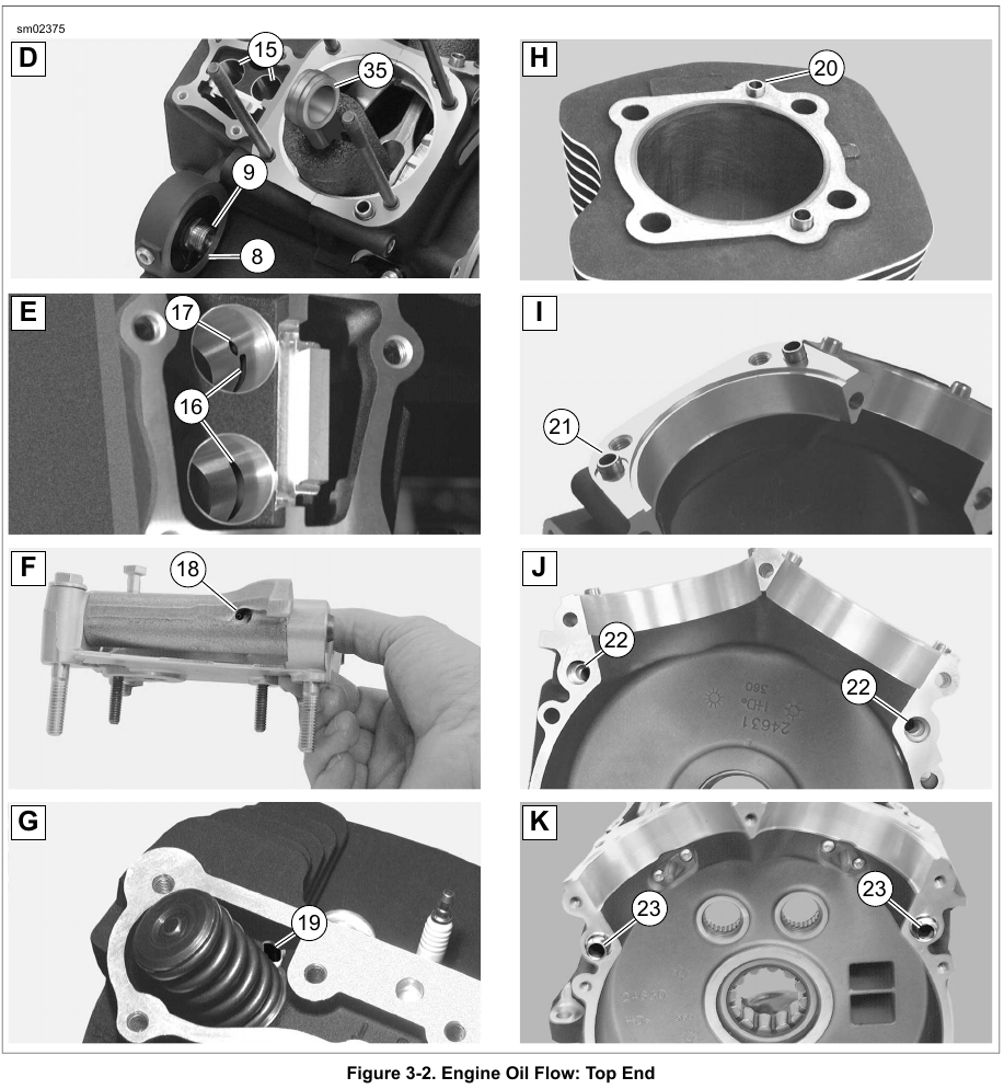
• Top end oil flow is shown in Figure 3-2.
• Bottom end oil flow is shown in Figure 3-3.
Oil traveling through the horizontal passage (A11-A12) at the top of the cam support plate (en route to the cylinders) also passes through a hole at the top of each camshaft bore. This oil lubricates the journals of the plain bearing cams. Some oil flowing to the rear cylinder sprays through a pin hole to lubricate the secondary cam chain.
Oil to the rear cylinder also travels down the vertical passage (A27) at the rear of the cam support plate. This oil exits a hole on the outboard side to supply oil to the primary cam chain tensioner (A28).
The flow of oil in the vertical passage (A29) at the center of the cam support plate passes through a hole on the inboard side. This supplies oil to the secondary cam chain tensioner.
Oil also sprays through a pin hole (A30) to lubricate the primary cam chain. Oil then flows through a hole in the crankshaft bushing where it enters a passage in the crankshaft (L31).
Oil flows through the center of the crankshaft and through a cross passage into the right side of the flywheel. Oil enters the crank pin and exits through three holes to lubricate the lower rod bearing set.
Oil splash and mist created by flywheel rotation lubricates the crankshaft and the camshaft bearings in the right crankcase half. This same action serves to lubricate the sprocket shaft bearing in the left crankcase half (M32).
Since the oil mist also lubricates the cylinder walls, three holes on each side of the piston (in the area of the third ring land) evacuate excess oil scraped from the walls on the piston downstroke.
The piston jets (N33) receive oil from the intake lifter bores. They spray the underside of the piston for cooling of the piston crown and skirt area. A check valve in each jet opens only when the oil pressure reaches 12-18 psi (82.7-124.1 kPa), at which point the engine is operating above idle speed. Oil pressure at idle speeds will be 9-12 psi (62.1-82.7 kPa). At this pressure the valve remains closed to prevent over oiling and to provide proper system operating pressure.
Oil spray from each piston jet also enters a hole at the bottom of each pin boss (O34) to lubricate the piston pin. The spray also allows a portion of the oil to reach the upper rod bushing (D35).
Surplus oil falls back to the bottom of the flywheel compartment where it collects in the sump area (P36). Oil in the sump is drawn to the scavenge side of the oil pump (B35) through an internal channel (P37, C34).