Symptoms indicating a need for engine repair are often misleading. If more than one symptom is present, possible causes can be narrowed to make at least a partial diagnosis.
For example, an above normal consumption of oil could be caused by several mechanical faults. But when accompanied by blue-gray smoke from the exhaust and low compression, it indicates the rings need replacing. Low compression by itself is more likely to be caused by improperly seated or burned valves, not worn rings.
Certain “knocking” noises may occur because of loose bearings, others by piston slap. Piston slap is a condition where piston or cylinder or both are out of tolerance. This excessive clearance allows the piston to “slap” the cylinder as it moves up and down.
Most frequently, valves, rings, pins, bushings and bearings need attention at about the same time. If the symptoms indicate that any one of the above components is worn, service all related parts.
NOTE
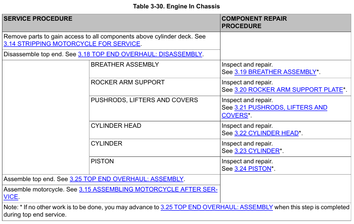
Servicing components in the cam compartment requires only partial disassembly. This can be done with the engine left in the chassis.
After disassembling as far as the cylinder heads you may find that bottom end repair is necessary. Bottom end service may require either partial or complete disassembly of the engine.
• To service the cam compartment, see 3.26 CAM COMPARTMENT AND COMPONENTS.
• To service components in the flywheel compartment, the engine must be removed and the crankcase halves split.
See 3.13 CAM COMPARTMENT SERVICE, Engine Removed From Chassis.
NOTE
During top end disassembly, the engine may be left in the chassis for service.
If servicing only cylinder head components, pistons, cylinders and/or upper rod bushings, two options are available depending upon engine status.
• 3.12 TOP END SERVICE, Engine in Chassis.
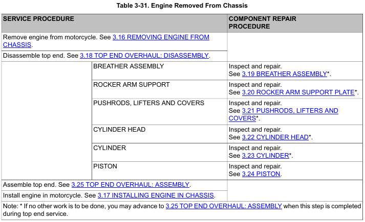
• 3.12 TOP END SERVICE, Engine Removed from Chassis.
1. Clean all residual oil and threadlocking compound from the threaded hole in the crankcase and threads of the oil filter adapter.
NOTE
The oil cooler adapter will fit in only one orientation. Match the positioning bosses (6) on the oil cooler adapter to the oil filter mount.
2. See Figure 3-12. Apply LOCTITE 246 MEDIUM STRENGTH/HIGH TEMPERATURE THREADLOCKER (blue) to the threads of the oil filter adapter (5).
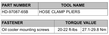
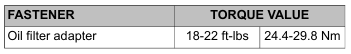
3. While holding oil cooler adapter in place, install the oil filter adapter (5) with the internal hex facing outward. Tighten to 18-22 ft-lbs (24.4-29.8 Nm).
4. Install the oil hoses and clamps.
5. Install new oil filter.
![]()
Do not operate the engine when the oil level is below the add mark on the dipstick at operating temperature. Engine damage will result. (00187b)
6. Start engine and check for oil leaks.
7. Perform engine oil level hot check.
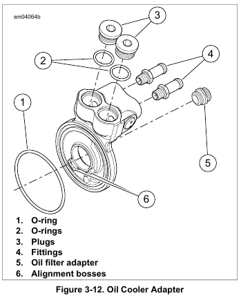
1. See Figure 3-12. Install plugs (3) and new O-rings (2).
2. Apply LOCTITE 565 THREAD SEALANT fittings (4). Install fittings:
a. Finger-tighten.
b. Turn 2-3 more turns.
1. See Figure 3-12.Remove plugs (3) and O-rings (2).
2. Remove oil cooler line fittings (4).
NOTE
Replace the oil cooler adapter if the thermostat malfunctions.
3. Clean the oil filter mount surface.
4. Clean the oil passages in solvent.
5. Inspect the oil passages and the oil cooler mount.
1. Place a drain pan under motorcycle.
2. Bend a cardboard funnel to route fluid away from regulator and oil cooler.
3. Use OIL FILTER WRENCH (Part No. HD-42311) to remove the oil filter.
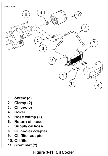
4. Remove the clamps from the oil hoses at the adapter.
5. See Figure 3-12. Remove the oil filter adapter (5).
6. Remove the oil cooler adapter and O-ring (1).