Author: Sam

  • 2015 Touring – TOP END OVERHAUL : DISASSEMBLY – PUSHRODS, LIFTERS AND COVERS

    NOTE

    Mark parts for location and orientation upon removal.

    1.  See Figure 3-19. Remove the intake and exhaust pushrods and pushrod covers:
    a. Remove pushrods.
    b. Remove pushrod covers.
    c. Remove three O-rings from pushrod covers and discard. If O-ring is missing from upper pushrod cover, make sure to dislodge it from the cylinder head bore.

    2. See Figure 3-20. Remove lifter covers:
    a. Using a crosswise pattern, remove four screws (1).
    b. Remove the lifter cover (2) and gasket. Discard gasket.

    3. Remove lifters:
    a. Remove the anti-rotation pin to free the hydraulic lifters.
    b. Remove the lifters and place in clean plastic bags to prevent contamination.

    4. For inspection and repair information, see 3.21 PUSHRODS, LIFTERS AND COVERS.


  • 2015 Touring – TOP END OVERHAUL : DISASSEMBLY – ROCKER ARM SUPPORT PLATE

    1. See Figure 3-15. Insert the blade of a small screwdriver into tab (1) of spring cap retainer. While pushing down on spring cap (2), rotate bottom of screwdriver toward outboard side to remove. Repeat step on second pushrod cover.

    2. Collapse upper and lower pushrod covers.

    NOTE

    Do not attempt to rotate the crankshaft by placing a socket on the crankshaft or compensating sprocket bolt.

    3. When removing the rocker arm support plate, both lifters must be on the base circle (lowest position) of the cam.
    Rotate the crankshaft using one of the methods presented below.
    a. With primary cover installed: Remove spark plugs.
    With the rear wheel raised, place the transmission in sixth gear and rotate rear wheel backward until the base circle is found.
    b. With primary cover removed: Remove spark plugs.
    Place the transmission in neutral. Using a large socket on the compensating sprocket retainer, rotate counterclockwise until the base circle is found.
    c. See Figure 3-16. With engine mounted in engine stand: Install CRANKSHAFT ROTATING WRENCH
    (Part No. HD-48283) on sprocket shaft and rotate counterclockwise until the base circle is found.

    4. Rotate engine until piston is at TDC of compression stroke.

    NOTE

    Breather baffle assembly is manufactured with gaskets attached. Any time the breather is disassembled, the baffle assembly must be replaced with a new assembly.

    5. See Figure 3-17. Remove breather assembly (arrow) and filter element from the rocker arm support plate. For inspection and repair information, see 3.19 BREATHER ASSEMBLY.

    6. Loosen the four rocker arm support plate bolts 1/4 turn at a time in the sequence shown. Remove the rocker arm
    support plate bolts with flat washers.

    7. Remove the rocker arm support plate assembly. For inspection and repair information, see 3.20 ROCKER ARM
    SUPPORT PLATE.

    8. See Figure 3-18. Remove and discard breather O-ring from rocker housing.

    NOTE

    If the other cylinder also requires service, find the cam base circle for that cylinder before disassembling.


  • 2015 Touring – TOP END OVERHAUL : DISASSEMBLY – ROCKER COVERS

    NOTE

    Dirt caked on cooling fins and other areas can fall into crankcase bore. It can also stick to subassemblies as parts are removed. Abrasive particles can damage machined surfaces or plug oil passageways. Clean parts before disassembly to prevent component damage.

    1. Use low pressure air to thoroughly clean exterior surfaces of engine prior to disassembly.
    2. See Figure 3-14. Following the sequence shown, alternately loosen the six rocker cover bolts. Remove the rocker
    cover bolts and their captive washers.
    3. Remove the rocker cover and gasket. Discard gasket.


  • 2015 Touring – TOP END OVERHAUL : DISASSEMBLY – GENERAL

    It is assumed that each step performed on one cylinder is automatically repeated on the other.

    To perform a complete top end overhaul, follow all steps listed in this section including inspection and repair procedures.

    Twin-Cooled engine: Drain coolant and remove upper coolant lines prior to disassembly. See C.5 COOLING SYSTEM REPAIR.

  • 2015 Touring – INSTALLING ENGINE IN CHASSIS – PROCEDURE

    1. Install oil pan, if removed. See 3.31 OIL PAN.

    2. Cover rocker covers of front and rear cylinders with foam padding or bubble pack.

    3. Cover lower frame tubes (both left and right side) with foam padding or bubble pack to prevent damage to frame tubes, brake line and main harness. A split loom conduit or a half shell of PVC tubing will also produce good results.

    4. Wrap rear master cylinder reservoir with foam padding or bubble pack.

    5. Install engine in chassis from right side. Set front of crankcase onto front engine mount crossmember. Engine must be forward far enough to clear two ring dowels in lower flange of transmission.

    6. Install new gasket and engage index pins in holes of transmission flange. Mate engine to transmission and fully engage two ring dowels at bottom of transmission flange.

    7. Install front engine mount assembly. Install but do not fasten crankcase to front engine mount bracket at this time. See 2.54 FRONT ENGINE MOUNT.

    8. Secure the engine:
    a. Hand-tighten four bolts (with flat washers) to secure transmission to crankcase. Install the shorter bolts at
    the top and the longer bolts at the bottom.
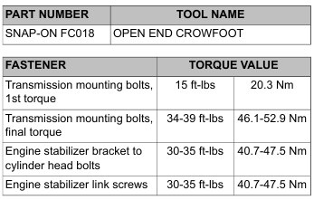
    b. Tighten the four transmission to crankcase bolts to 15 ft-lbs (20.3 Nm) in a crosswise pattern.

    NOTE

    For best results, use OPEN END CROWFOOT (Part No. Snap-On FC018) on upper transmission to crankcase bolts.
    c. Repeating the crosswise pattern, final tighten the four transmission to crankcase bolts to 34-39 ft-lbs (46.1-
    52.9 Nm).
    d. Secure engine to front engine mount. See 2.54 FRONT ENGINE MOUNT.

    NOTE

    Check each end of the stabilizer link for excessive wear prior to installation. The spherical ball end may rotate freely, but should not have any lateral movement. Replace the link if lateral movement exists.

    e. Secure engine stabilizer link bracket to front cylinder head. Tighten to 30-35 ft-lbs (40.7-47.5 Nm).
    f. Secure stabilizer link to frame weldment. Tighten to 30-35 ft-lbs (40.7-47.5 Nm).

    9. Remove jack and wooden block from under oil pan.

    10. Install oil filter. See 1.6 ENGINE OIL AND FILTER.

    11. Install stator and rotor. See 7.21 ALTERNATOR.

    12. Install primary chaincase. See 5.5 PRIMARY CHAINCASE HOUSING.

    13. Allow main harness to hang below lower frame tube at front of motorcycle.

    14. Install oil pressure switch/sender. See 7.25 OIL PRESSURE SWITCH OR SENDER.

    15. Install CKP sensor. See 7.17 CRANKSHAFT POSITION SENSOR (CKP).

    16. Install voltage regulator. See 7.20 VOLTAGE REGULATOR.

    17. Twin-Cooled models: See C.5 COOLING SYSTEM REPAIR, Upper Coolant Line Installation.
    a. Connect coolant manifolds to cylinder head lines.
    b. Install clamp securing hoses to front cylinder head.

    18. Release disconnected branches of main harness from top of wire trough.

    19. Install induction module. See 4.13 INDUCTION MODULE.

    20. Install purge solenoid hose, if equipped, to induction module. See 4.20 EVAPORATIVE EMISSIONS CONTROL SYSTEM.

    21. Install spark plugs. Install spark plug cables. See 1.19 SPARK PLUGS.

    22. Install backplate and air cleaner. See 4.5 AIR CLEANER ASSEMBLY.

    23. Install fuel tank. See 4.6 FUEL TANK.

    24. Install exhaust system. See 4.18 EXHAUST SYSTEM.

    25. Fill and check oil level. See 1.6 ENGINE OIL AND FILTER.


  • 2015 Touring – REMOVING ENGINE FROM CHASSIS – PROCEDURE

    1. Remove exhaust system. See 4.18 EXHAUST SYSTEM.

    2. Remove fuel tank. See 4.6 FUEL TANK.

    3. Remove air cleaner and backplate. See 4.5 AIR CLEANER ASSEMBLY.

    4. Remove spark plugs. See 1.19 SPARK PLUGS.

    5. Remove induction module. See 4.13 INDUCTION MODULE.

    6. Gather disconnected branches of main harness and tape to top of wire trough.

    7. Twin-Cooled models: See C.5 COOLING SYSTEM REPAIR, Upper Coolant Line Removal.
    a. Disconnect coolant manifolds from cylinder head lines.
    b. Remove clamp securing hoses to front cylinder head. Move hoses out of the way.

    8. Remove voltage regulator. See 7.20 VOLTAGE REGULATOR.

    9. Remove CKP sensor. See 7.17 CRANKSHAFT POSITION SENSOR (CKP).

    10. Remove oil filter. See 1.6 ENGINE OIL AND FILTER.

    11. Remove oil pressure switch/sender. See 7.25 OIL PRESSURE SWITCH OR SENDER.

    12. Coil main harness and allow to hang below lower frame tube at front of motorcycle.

    13. Remove primary chaincase. See 5.5 PRIMARY CHAINCASE HOUSING.

    14. Remove rotor and stator. See 7.21 ALTERNATOR.

    15. Wrap rear master cylinder reservoir with foam padding or bubble pack.

    16. Cover lower frame tubes (both left and right side) with foam padding or bubble pack to prevent damage to frame tubes, brake line and main harness. A split loom conduit or a half shell of PVC tubing will also produce good results.

    17. Cover rocker covers with foam padding or bubble pack.

    18. Place a jack under the oil pan and use a block of wood between the jack and oil pan to distribute pressure across the length of the casting. Raise the jack until firm contact is made with the bottom of the oil pan.

    19. Remove top engine stabilizer bracket from front cylinder head. Remove stabilizer link from frame weldment.

    20. Remove four bolts (with flat washers) in a crosswise pattern to free transmission from crankcase.

    21. Remove front engine mount. See 2.54 FRONT ENGINE MOUNT.

    22. Move engine forward far enough to clear two ring dowels at bottom of transmission flange. Raise engine and remove from right side of motorcycle. Exercise caution to avoid contact with rear brake line, rear brake master cylinder reservoir, and main harness.

    23. See Figure 3-13. Using the TWIN CAM 88 CRADLE (Part No. HD-42310-2), install engine in BENCH STAND (Part No. HD-42310) or ROLLING STAND (Part No. HD-43646A).

    24. Thoroughly wipe all engine oil from pockets in crankcase flange. Remove gasket and two index pins from transmission flange. Discard gasket.

    25. Remove and clean the oil pan under any of the following conditions. See 3.31 OIL PAN.
    a. Metal debris is found in the engine or crankcase.
    b. Oil contamination is suspected.
    c. A complete engine overhaul is being performed as a result of a major engine failure.
    d. The engine is being replaced with a new one.

  • 2015 Touring – ASSEMBLING MOTORCYCLE AFTER SERVICE – PROCEDURE

    After Top End Service

    1. Secure top engine stabilizer bracket to front cylinder head. Tighten to 30-35 ft-lbs (40.7-47.5 Nm).

    NOTE

    Check each end of the stabilizer link for excessive wear before installation. The spherical ball end may rotate freely, but should not have any lateral movement. Replace the link if lateral movement exists.

    2. Secure engine stabilizer link to frame weldment. Tighten to 30-35 ft-lbs (40.7-47.5 Nm).

    3. Secure horn bracket to front cylinder head.

    4. Release disconnected branches of main harness from top of wire trough.

    5. Install induction module. See 4.13 INDUCTION MODULE.

    6. Continue with steps under After Cam Compartment Service.

    After Cam Compartment Service

    1. Twin-Cooled models: See C.5 COOLING SYSTEM REPAIR, Upper Coolant Line Installation.
    a. Connect coolant manifolds to cylinder head lines.
    b. Install clamp securing hoses to front rocker cover.

    2. Install purge solenoid hose, if equipped, to induction module. See 4.20 EVAPORATIVE EMISSIONS CONTROL
    SYSTEM.

    3. Install spark plugs and connect spark plug cables.

    4. Install air cleaner assembly. See 4.5 AIR CLEANER ASSEMBLY.

    5. Install fuel tank. See 4.6 FUEL TANK.

    6. Install exhaust system. See 4.18 EXHAUST SYSTEM.


  • 2015 Touring – STRIPPING MOTORCYCLE FOR SERVICE – PROCEDURE

    Cam Compartment Service Only

    1. Remove exhaust system. See 4.18 EXHAUST SYSTEM.

    2. Remove fuel tank. See 4.6 FUEL TANK.

    3. Remove air cleaner and backplate. See 4.5 AIR CLEANER ASSEMBLY.

    4. Remove spark plugs. See 1.19 SPARK PLUGS.

    5. Remove purge solenoid hose, if equipped, from induction module. See 4.20 EVAPORATIVE EMISSIONS CONTROL SYSTEM.

    6. Twin-Cooled models: See C.5 COOLING SYSTEM REPAIR, Upper Coolant Line Removal.
    a. Disconnect coolant manifolds from cylinder head lines.
    b. Remove clamp securing hoses to front cylinder head. Move hoses out of the way.

    Top End Service

    1. Complete all steps under Cam Compartment Service Only.

    2. Remove induction module. See 4.13 INDUCTION MODULE.

    3. Gather disconnected branches of main harness and tape to top of wire trough to keep out of the way.

    4. Remove two screws to release top engine stabilizer bracket from front cylinder head. Remove screw to release
    stabilizer link from frame weldment.