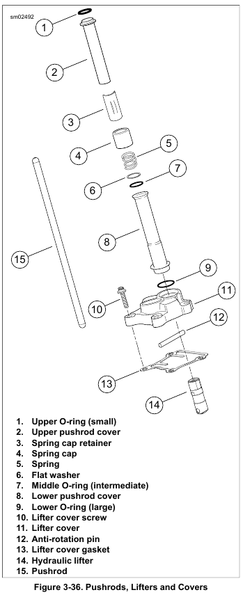
1. See Figure 3-36. Separate upper (2) and lower (8) pushrod covers.
2. Remove and discard O-ring (9).
3. Remove O-ring (1). Slide O-ring (7), flat washer (6), spring (5) and spring cap (4) from upper pushrod cover (2). Discard O-rings.
1. See Figure 3-36. Separate upper (2) and lower (8) pushrod covers.
2. Remove and discard O-ring (9).
3. Remove O-ring (1). Slide O-ring (7), flat washer (6), spring (5) and spring cap (4) from upper pushrod cover (2). Discard O-rings.
1. Place the rocker arms into position on the rocker arm support plate.
2. Install rocker arm shafts:
a. Push un-notched ends of rocker arm shafts into right side of support plate and then into rocker arms.
b. As they approach their fully installed positions, rotate shafts until notches are aligned with bolt holes in
support plate.
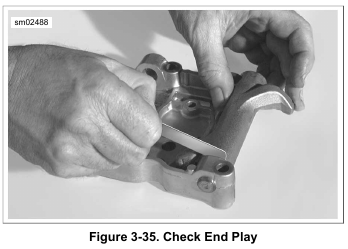
3. See Figure 3-35. Check for proper end play.
a. Insert a feeler gauge between the rocker arm and support plate.
b. Repeat measurement on other rocker arm.
c. Replace the rocker arm, rocker arm support plate or both if end play exceeds 0.025 in. (0.635 mm).
4. Install the four bolts with flat washers in the rocker arm support plate. Remember that the two bolts on the pushrod side (right) must engage the notches in the rocker arm shafts for proper assembly.
Inspection
1. Clean all parts in a non-volatile cleaning solution or solvent. Dry parts with low pressure compressed air.
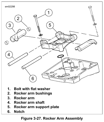
2. See Figure 3-27. Check rocker arms (3) for uneven wear or pitting where contact is made with the valve stem tips. Check for concave wear where rocker arms contact the pushrod ends. Replace rocker arm if excessive wear is found.
3. Verify that oil holes in rocker arms and rocker arm support plate (5) are clean and open.
4. Inspect rocker arm shafts (4) for scratches, burrs, scoring or excessive wear. Replace as necessary.

Rocker Shaft Fit
1. See Figure 3-28. Measure the inside diameter of the rocker arm support plate bore.
2. See Figure 3-29. Measure the outside diameter of the rocker arm shaft where it fits in the bore.
3. Repeat the measurement on opposite side of support plate and shaft. Replace shaft or support plate if clearance
exceeds service wear limit of 0.0035 in (0.089 mm).


Rocker Arm Shaft to Bushing
1. Check rocker arm shaft to bushing fit.
a. See Figure 3-30. Measure the inside diameter of the rocker arm bushing.
b. See Figure 3-31. Measure the outside diameter of the rocker arm shaft where it rides in the bushing.
2. Repeat measurement on opposite side of rocker arm and shaft. Replace shaft or bushings if clearance exceeds
service wear limit of 0.0035 in (0.089 mm).


Replace Rocker Arm Bushings
NOTE
Bushing replacement and reaming must be done one at a time to achieve proper alignment. Follow all steps for one bushing and then repeat for the other bushing.
1. See Figure 3-32. Remove bushing from rocker arm:
a. Turn a 9/16-18 tap (2) into bushing until tight.
b. Place rocker arm under ram of arbor press with tap at bottom.
c. Slide a discarded rocker arm shaft (1) through open end of rocker arm until contact is made with tap.
d. Using shaft as driver (and untapped bushing as pilot), press against shaft until both tap and bushing are free.
2. See Figure 3-33. Using a suitable driver, press new bushing into side of rocker arm until flush with casting. Be sure to orient bushing so that split line faces top of rocker arm.
NOTE
Never back the reamer out of rocker arm or new bushing will be damaged.
3. Ream bushing:
a. See Figure 3-34. Lock rocker arm in a vise using brass jaw inserts or shop towels to prevent casting damage. Note that old bushing on drive side of reamer as pilot.
b. Rotate reamer until the new bushing on the far side is reamed.
c. Continuing in the same direction, draw drive side of reamer from new bushing.
4. Repeat steps to remove, install and ream second bushing.


1. See Figure 3-27. Remove four bolts and flat washers (1) from the rocker arm support plate (5).
2. Remove the rocker arm shafts (4) so that the notched ends exit the rocker arm support plate (5) first. Use a hammer and brass drift if necessary. Mark the shafts so that they are installed in their original locations at time of assembly.
3. Remove the rocker arms. Mark the rocker arms to indicate location.
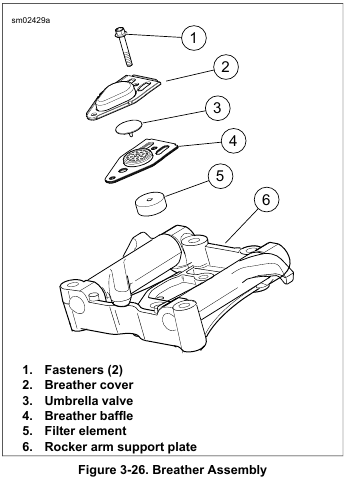
See Figure 3-26. Install breather assembly and rocker cover using new baffle assembly. See 3.25 TOP END OVERHAUL: ASSEMBLY, Breather and Rocker Cover.

1. Clean cover and screws in a non-volatile cleaning solution or solvent. Dry parts with low pressure compressed air.
2. Set a straightedge diagonally across the length of the breather cover intersecting the opposite corners of the gasket surface.
3. Slide a feeler gauge beneath the straightedge to check the breather cover flatness.
4. Repeat the step checking the opposite diagonal.
5. Replace the breather cover if warpage exceeds 0.005 in. (0.13 mm).
NOTE
See Figure 3-26. Breather baffle assembly is manufactured with gaskets attached. Replacement part is supplied with the filter element (5) and umbrella valve (3). Any time the breather is disassembled, the baffle assembly must be replaced with a new assembly.
1. Remove rocker cover. See 3.18 TOP END OVERHAUL: DISASSEMBLY, Rocker Covers.
2. Remove two fasteners (1) and remove breather cover (2).
3. Remove breather baffle (4). Discard breather baffle, filter element (5) and umbrella valve (3).
1. Place clean shop towels over crankcase bore. This prevents the piston pin retaining ring from falling into the
crankcase.
NOTE
It is not necessary to remove both piston pin retaining rings for piston removal.
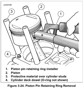
2. See Figure 3-24. Using PISTON PIN RETAINING RING INSTALLER (Part No. HD-42317-A), remove and discard one piston pin retaining ring.
a. Insert tool (1) into piston pin bore. Position claw on tool in slot of piston (2) (directly under retaining ring).
b. Squeeze handles of tool together. Pull retaining ring from bore. Discard retaining ring.
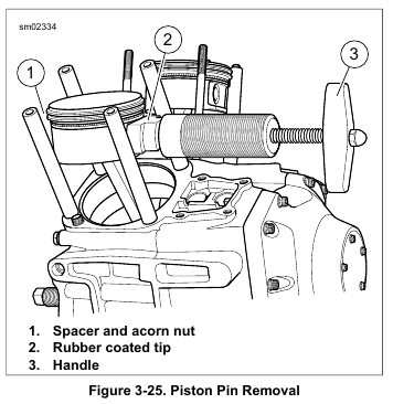
3. See Figure 3-25. Remove the piston pin. If piston pin is difficult to remove, use PISTON PIN REMOVER (Part No. HD-42320-B).
4. Remove the piston. Hold the connecting rod upright to prevent it from striking the crankcase.
5. Place a 3.0 in. (76.2 mm) long piece of foam-type water pipe insulation around connecting rod to prevent damage. Use material with an I.D. of 1.0 in. (25.4 mm).
6. Turn the piston over. Mark the pin boss with the letters F(ront) or R(ear) to identify location.
7. For inspection information, see 3.24 PISTON.
8. Complete engine repair:
a. If performing a top end overhaul only, see 3.25 TOP END OVERHAUL: ASSEMBLY.
b. If performing a complete engine overhaul, see 3.26 CAM COMPARTMENT AND COMPONENTS
and 3.28 CRANKCASE DISASSEMBLY AND REPAIR.
1. Raise the cylinder just enough to place clean shop towels under the piston. This will prevent any dirt or debris, such as broken ring pieces, from falling into the crankcase bore.
NOTE
Do not bend the cylinder studs. Even a slight bend or nick can cause a stress riser leading to stud failure.
2. Carefully remove the cylinder. Exercise caution to avoid bending the cylinder studs. As the piston becomes free of the cylinder, hold it upright to prevent it from striking the studs or dragging across the stud thread area.
3. Mark cylinder FRONT or REAR as appropriate.
4. Slide approximately 6.0 in (152 mm) of plastic tubing, rubber hose or conduit over each cylinder stud. Use material with ID of 0.5 in (12.7 mm) to protect cylinder studs and piston from damage.
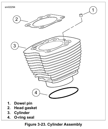
5. See Figure 3-23. Remove O-ring seal (4) from the bottom of the cylinder liner. Discard O-ring seal.
6. See Figure 3-24. Remove O-ring from dowel pin (4) on base of cylinder deck. Discard O-ring.
7. For inspection and repair information, see 3.23 CYLINDER.

1. See Figure 3-21. Following the sequence shown, loosen the six rocker housing bolts. Remove rocker housing bolts.
2. Remove rocker housing and gasket. Discard gasket.
NOTE
To prevent distortion of the cylinder head, cylinder and cylinder studs, gradually loosen the cylinder head bolts in the specified sequence.
3. See Figure 3-22. Remove cylinder head bolts:
a. Alternately loosen cylinder head bolts 1/4 turn at a time the sequence shown.
b. Remove the cylinder head bolts.
4. Remove cylinder head and head gasket.
NOTE
Save the cylinder head gasket (if salvageable) for use with the CYLINDER TORQUE PLATES (Part No. HD-42324-A) when measuring, boring or honing of the cylinder is required.
5. For inspection and repair information, see 3.22 CYLINDER HEAD.

