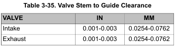
• Verify correct valve stem to valve guide clearance before refacing. If new guides must be installed, complete that task before refacing valve seats. Refer to Table 3-35.
• This procedure is not based on the lapping of valves. The end result is an interference fit between the 45 degree valve face and the valve seat which will be 46 degrees.
1. Remove carbon deposits from valve head, face and stem with a wire wheel. Do not remove any metal. Carbon left on stem may affect alignment during valve refacing.
2. Polish valve stem with steel wool or crocus cloth to remove marks left by wire wheel.
3. Grind valve face to a 45 degree angle using a valve grinding machine.
NOTES
• Do not remove any more metal than necessary to clean up and true the valve face.
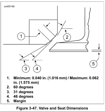
• Replace the valve if margin is less than 0.0313 in (0.795 mm). See Figure 3-47.
4. Wipe valve seats and valve faces clean. Install the valve into the valve guide. Push on head of valve until it contacts the valve seat.
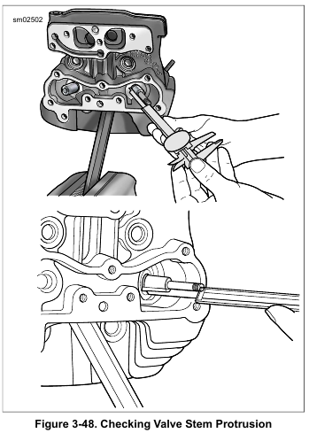
5. See Figure 3-48. Measure valve stem protrusion.
a. Use a dial caliper to check the distance from the top of the valve stem to the machined area on the cylinder head.
b. If protrusion exceeds 2.069 in. (52.553 mm), replace the valve, valve seat or cylinder head as necessary.
NOTE
Do not shorten the valve by grinding the end of the stem.
Grinding removes the hardened case which results in accelerated wear.
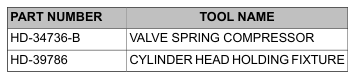
6. Secure cylinder head for servicing.
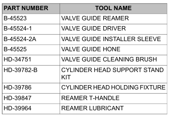
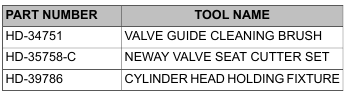
a. Thread 12 mm end of CYLINDER HEAD HOLDING FIXTURE (Part No. HD-39786) into cylinder head spark plug hole.
b. Clamp fixture in vise and further tighten cylinder head onto the fixture to prevent any movement during operation.
c. Place cylinder head at a 45 degree angle or one that offers a comfortable working position.
7. To determine the correct location of the 46 degree valve seat in the head, measure the diameter of the valve head and subtract 0.080 in. (2.032 mm) from that number.
8. Set the dial caliper to the lesser measurement and lock down for quick reference. This is the diameter of the valve seat.
9. Use a permanent marker to highlight the valve seat area.
Highlight all three angles. Allow marker to dry before proceeding.
• Always verify cutter blades and cutter pilot are clean before beginning the cutting process. The correct cleaning brush is supplied with the Neway tool set.
• Always verify the inside of the valve guide is clean by using VALVE GUIDE CLEANING BRUSH (Part No. HD-34751).
NOTES
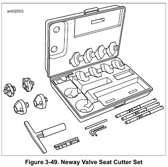
10. See Figure 3-49. Obtain the NEWAY VALVE SEAT CUTTER SET (Part No. HD-35758-C). Choose the cutter pilot that fits properly into the valve guide hole. Securely seat the pilot by pushing down and turning using the installation tool supplied in the tool set.
11. Choose the proper 46 degree cutter (intake or exhaust) and gently slide the cutter onto the pilot. Do not drop the cutter onto the seat.
12. While applying a constant and consistent pressure, remove only enough metal to provide a uniform finish and to remove pitting.
NOTES
• If the width of the clean-up cut is greater on one side of the seat than the other, the guide may need to be replaced due to improper installation.
• If a groove cut completely around the seat is apparent, slightly stagger the blades of the cutter.
13. Measure the 46 degree cut at the outermost edge at the widest point of the circle to determine what cut will be made next.
a. If the outer diameter is too large, use the 31 degree cutter to lower the valve seat.
b. If the outer diameter is too small, use the 46 degree cutter to widen the valve seat or move it away from the port.
NOTES
• Because the OD measurement of the valve seat is used as a reference point it will usually be necessary to use the 31 degree cutter following the initial 46 degree cut.
• Always highlight the valve seat with the permanent marker in order to better view the location of the 46 degree valve seat.
14. If the location of the valve seat is not correct, repeat steps 10 through 13.
15. When a complete clean-up of the 46 degree angle is accomplished and the width is at least 0.062 in. (1.575 mm), proceed to the next step.
16. Select the proper 60 degree cutter and gently slide the cutter down the cutter pilot to the valve seat.
17. Remove just enough material to provide an even valve seat width of 0.040-0.062 in. (1.016-1.575 mm).
18. Remove cutter and cutter pilot.
19. Insert valve into the cylinder head. Use thumb pressure against valve to hold it closed.
20. Completely fill the port with solvent to verify proper seal between valve and valve seat.
NOTE
Hold pressure against the valve for a minimum of 10 seconds. If any leakage occurs, examine the valve and valve seat for irregularities or defects. If necessary repeat the above valve grinding or valve seat cutting process.
21. Repeat the process on any valve seat that needs service.
22. Clean valves, cylinder head and valve seats in solvent. Follow up with a thorough wash in hot soapy water.
23. Dry parts with low pressure compressed air.