Removal
NOTES
• If valve guide replacement is necessary, always install new guide before refacing valve seat.
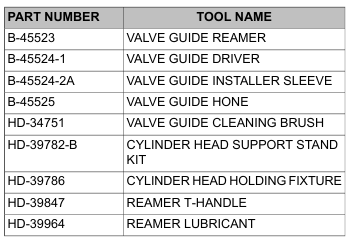
• CYLINDER HEAD SUPPORT STAND KIT (Part No. HD-39782-B) ensures that valve guide and seat are perpendicular. Not keeping cylinder head valve guide bore perpendicular will result in damage during the press procedure.
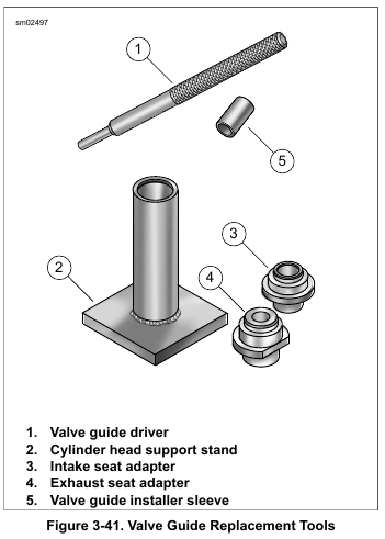
1. See Figure 3-41. Prepare cylinder head for valve guide replacement.
a. Obtain CYLINDER HEAD SUPPORT STAND KIT (Part No. HD-39782-B).
b. Insert sleeve of appropriate seat adapter (3 or 4) into tube at top of support stand (2).
c. Position cylinder head so that valve seat is centered on seat adapter.
NOTE
Always press valve guide toward combustion chamber. Carbon buildup on combustion chamber side of guide can damage cylinder head bore. this may prevent a proper interference fit.
2. Remove and discard lock ring from valve guide groove.
NOTE
Lock ring is present on OEM intake and exhaust valve guides.
3. Insert VALVE GUIDE DRIVER (Part No. B-45524-1) (1)
into valve guide bore.
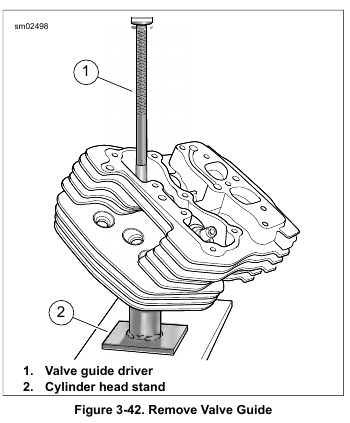
4. See Figure 3-42. Center valve guide driver under ram of arbor press. Apply pressure until valve guide drops free of cylinder head. Discard valve guide.
Installation
1. Check valve guide to valve bore interference fit.
a. Measure the outside diameter of a new standard valve guide.
b. Measure the cylinder head valve guide bore. The valve guide should be 0.0020-0.0033 in. (0.051-0.084 mm) larger than the bore.
c. If interference is not within specification, select one of the following oversize guides: 0.001 in. (0.025 mm), 0.002 in. (0.05 mm) or 0.003 in. (0.08 mm).
NOTE
Pressing out guide may remove material. Using the next larger size is not uncommon to guarantee proper interference fit.
2. Select an oversize guide that will provide the correct interference fit.
NOTE
The support stand ensures that valve guide and seat are perpendicular. This alignment helps prevent damage during the press procedure.
3. Prepare cylinder head for valve guide replacement.
a. See Figure 3-41. Insert sleeve of the appropriate seat adapter (3 or 4) into tube at top of support stand (2).
Position cylinder head so that valve seat is centered on seat adapter.
b. Apply a thin film of petroleum jelly to lightly lubricate external surface of valve guide.
c. Start valve guide into bore.
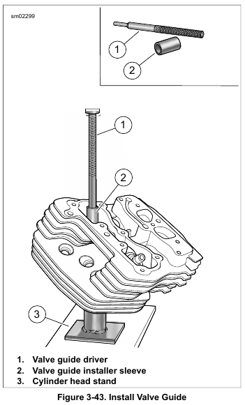
d. See Figure 3-43. Place VALVE GUIDE INSTALLER SLEEVE (Part No. B-45524-2A) (2) over valve guide and then insert valve guide driver (1) into sleeve.
e. Center valve guide driver under ram of arbor press and apply pressure only until valve guide is started in bore and then back off ram slightly to allow guide to center itself.
NOTE
Always back off ram to allow the valve guide to find center. Pressing guide into cylinder head in one stroke can bend driver, break guide, distort cylinder head casting and/or damage cylinder head valve guide bore.
f. Verify that support stand (3) and driver (1) are square. Center driver under ram and press valve guide further into bore, then back off ram again to allow valve guide to center itself.
g. Repeat previous step until installer sleeve contacts machined area of cylinder head.
h. Install new lock ring into valve guide groove. Verify that lock ring is square and fully seated in the groove.
4. Secure cylinder head for service.
a. Thread 12 mm end of CYLINDER HEAD HOLDING FIXTURE (Part No. HD-39786) into cylinder head spark plug hole.
b. Clamp tool in vise at a 45 degree angle or one that offers a comfortable working position.
NOTE
Valve guides are reamed to within 0.0005-0.0001 in. (0.013-0.0025 mm) under finished size.
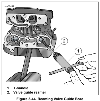
5. See Figure 3-44. Ream the guide.
a. Install REAMER T-HANDLE (Part No. HD-39847) (1) on VALVE GUIDE REAMER (Part No. B-45523) (2).
b. Apply a liberal amount of REAMER LUBRICANT (Part No. HD-39964) to valve guide bore and reamer. Start reamer into bore.
NOTE
Never turn reamer counterclockwise.
c. Apply slight pressure on reamer while rotating clock wise. Squirt additional lubricant onto reamer and into guide as necessary.
NOTE
For best results, do not push reamer or apply pressure to the reamer handle. Excessive pressure results in a rough cut and the bore will be tapered if pressure is not centrally applied.
d. Continue rotating reamer T-handle until entire bit has passed through valve guide bore.
e. Remove T-handle from reamer, and carefully draw out reamer through combustion chamber side of valve guide.
6. Remove metal shavings with low pressure compressed air.
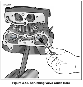
7. See Figure 3-45. Clean valve guide bore with the VALVE GUIDE CLEANING BRUSH (Part No. HD-34751).
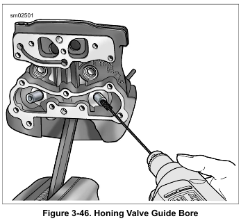
8. See Figure 3-46. Hone bore to finished size.
a. Install VALVE GUIDE HONE (Part No. B-45525) in a high-speed electric drill.
b. Apply reamer lubricant to stones of hone and valve guide bore.
c. Start stones of hone into bore.
d. Rotate the hone while moving the stones through the entire length of the bore for 10-12 complete strokes. Work for a crosshatch pattern of approximately 60 degrees.
9. Remove debris with low pressure compressed air. Clean with the VALVE GUIDE CLEANING BRUSH (Part No. HD-34751).
NOTE
Always check valve stem to valve guide clearance after honing.
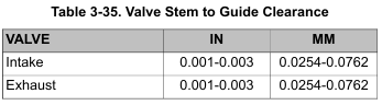
10. Check valve stem to valve guide clearance. Refer to Table 3-35. If the clearance is not within specification, repeat the honing process and recheck.
11. Clean cylinder head assembly.
a. Using cleaning solvent, thoroughly clean cylinder head and valve guide bore.
b. Scrub valve guide bore with the VALVE GUIDE CLEANING BRUSH (Part No. HD-34751). For best results, clean the valve guide bore with the type of swabs or patches found in gun cleaning kits and a thin engine oil.
c. Continue to wipe bore until a clean cloth shows no evidence of dirt or debris. Follow up with a thorough wash in hot soapy water.
12. Dry parts with low-pressure compressed air.
Leave a Reply