1. Secure cylinder head for service.
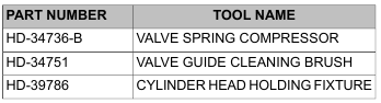
a. Thread 12 mm end of CYLINDER HEAD HOLDING FIXTURE (Part No. HD-39786) into cylinder head spark plug hole.
b. Clamp tool in vise at a 45 degree angle or one that offers a comfortable working position.
NOTE
At the time of disassembly, all parts should have been marked or tagged so that they are installed on the same valve (and in the same head).
2. Run the VALVE GUIDE CLEANING BRUSH (Part No. HD-34751) through the valve guide bore to verify cleanliness.
3. Apply a liberal amount of SCREAMIN’ EAGLE ASSEMBLY LUBE to valve stem.
4. Install the valve into the cylinder head.
5. To distribute the assembly lube evenly around the valve stem and guide, hand spin the valve as it is installed. Work the valve back and forth in the bore to verify that it slides smoothly and seats properly.
6. Remove the valve and apply a second coat of SCREAMIN’ EAGLE ASSEMBLY LUBE to the valve stem. Install the valve.
Failure to install plastic capsule can cause the valve stem seal to catch the edge of the valve stem keeper groove. The resulting damage can cause leakage around the valve stem, excessive oil consumption and valve sticking. (00535b)
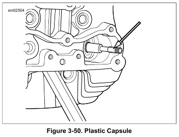
7. See Figure 3-50. Hold valve against the valve seat. Slide plastic capsule over valve stem tip and keeper groove.
8. Apply a very thin film of SCREAMIN’ EAGLE ASSEMBLY LUBE to capsule.
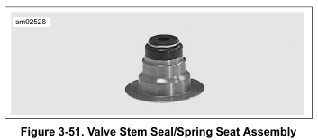
9. See Figure 3-51. Slide new valve stem seal/spring seat over capsule and down valve stem until seated against cylinder head casting. Remove capsule from valve stem tip.
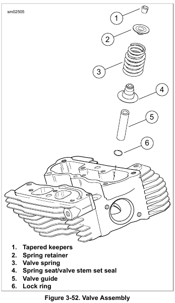
10. See Figure 3-52. Apply a liberal amount of SCREAMIN’ EAGLE ASSEMBLY LUBE to valve stem tip and keeper groove (1).
11. With the smaller diameter coils topside, install the valve spring (3). Place the spring retainer (2) on top of the valve spring.
12. Install keepers:
a. Place VALVE SPRING COMPRESSOR (Part No. HD-34736-B) over cylinder head so that the blunt end is centered on the valve head and adapter at end of
forcing screw is seated on the valve spring retainer.
b. Rotate forcing screw to compress valve spring.
c. With the tapered side down, fit the keepers into the valve stem groove. For best results, apply a dab of grease to the inboard side of the keepers before
installation and use a magnetic rod for easy placement.
d. Arrange tapered keepers so that the gaps are evenly spaced and release valve spring compression.
13. Tap the end of the valve stem once or twice with a soft mallet to be sure that tapered keepers are tightly seated.
14. Install the other valve and components.
15. Twin-Cooled models: Install fittings and lines to cylinder head. See C.5 COOLING SYSTEM REPAIR, Upper Coolant Line Installation.
16. Release the cylinder head holding fixture from the vise.
Remove fixture tool from spark plug hole.
17. Cover the cylinder head to protect it from dust and dirt until time of installation.
Leave a Reply