Two illustrations accompany this explanation.
Cam support plate oil flow is shown in Figure 3-1.
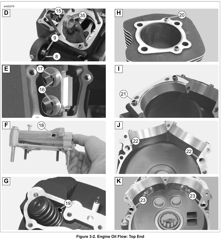
Top end oil flow is shown in Figure 3-2.
Oil flows from the oil pan through an internal passageway at the front of the transmission housing, and enters the lower passageway (A1) cast into the rear right side of the crankcase. Oil exits a hole in the crankcase flange (B2). It then enters a hole on the inboard side of the cam support plate. Passing through a channel in the cam support plate (A3), oil enters the feed side of the oil pump. See 3.5 OIL PUMP OPERATION. The feed gerotors of the pump direct the flow up a second channel in the cam support plate (A4).
A passage in this channel connects to a pressure relief valve mounted in the bypass port of the cam support plate (A5). When the oil pressure exceeds the setting of the relief valve spring 35 psi (241.3 kPa), the orifice opens to bypass excess oil back to the feed side of the pump (A3).
Oil not returned to the oil pump feed side exits a hole on the inboard side of the cam support plate. Oil then flows through a hole in the crankcase flange (B6). Oil flows through a passageway in the crankcase and exits the lower off-center hole in the oil filter mount (D8). The oil pressure sending unit (B7) is also connected to this passage.
After circulating through the oil filter, the flow is directed back into the crankcase through the center hole in the oil filter mount (D9). Exiting a passageway in the crankcase through a hole in the crankcase flange (B10), the flow of oil reenters the cam support plate.
Filtered oil is then routed to the top and bottom ends of the engine as described in 3.4 ENGINE OIL FLOW, Top End and 3.4 ENGINE OIL FLOW, Bottom End which follow.

Leave a Reply