Author: Sam

  • 2015 Touring – GAUGES AND INSTRUMENTS: ROAD KING MODELS – SPEEDOMETER

    Removal

    1. Remove main fuse. See 7.3 SYSTEM FUSES AND RELAYS.

    2. Remove seat. See 2.30 SEAT.

    3. Remove console. See 4.6 FUEL TANK, Console.

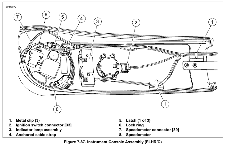
    4. See Figure 7-87. Remove speedometer connector (7).

    5. Remove anchored cable strap (4) from speedometer.

    6. Gently pry three latches (5) upward to release lock ring (6) from back of speedometer.

    7. Remove speedometer from top side of console.

    8. Remove rubber gasket from speedometer bore.

    Installation

    1. Lubricate groove in rubber gasket with isopropyl alcohol or glass cleaner. Place the gasket into position around the console speedometer bore.

    2. Install speedometer into rubber gasket. Lubricate gasket with isopropyl alcohol or glass cleaner, if necessary. The speedometer should fit snugly against the gasket without movement.

    3. See Figure 7-87. Place lock ring over back of speedometer aligning two slots with console bosses. Press latches (5) down until they lock into position.

    4. Connect speedometer connector (7).

    5. Insert anchored cable strap (4).

    NOTE

    Avoid pinching wire harness and vent tube while installing console.

    6. Install console. See 4.6 FUEL TANK, Console.

    7. Install seat. See 2.30 SEAT.

    8. Install main fuse. See 7.3 SYSTEM FUSES AND RELAYS.


  • 2015 Touring – GAUGES AND INSTRUMENTS: ROAD KING MODELS – FUEL GAUGE

    Removal

    1. Remove main fuse. See 7.3 SYSTEM FUSES AND RELAYS.

    2. Draw fuel gauge connector out of tunnel under left side of fuel tank and disconnect.

    3. Remove terminals from connector housing. See A.21 TYCO 070 MULTILOCK UNSEALED CONNECTOR.

    4. Remove convoluted tubing from wires.

    5. Remove the gauge from the fuel tank. Do not twist during removal. Pull upward just far enough to free the gauge from the fuel tank.

    6. Remove fuel gauge from motorcycle while feeding wires and terminals up through tube.

    7. If reusing gauge, inspect rubber gasket for damage.
    Replace gasket if necessary. Install new seal with flat side contacting edge of gauge.

    Installation

    1. Place new fuel gauge assembly next to discarded unit and cut wires to proper length.

    2. Crimp new pin terminals onto wires. See A.21 TYCO 070 MULTILOCK UNSEALED CONNECTOR.

    3. Install gauge:
    a. Feed wires down into tube while lowering gauge into position.
    b. When terminals exit bottom of fuel tank, gently pull wires while lowering the fuel gauge.

    NOTE

    Do not twist the gauge during installation.

    c. Hold the gauge firmly and press downward until it snaps in place.

    4. Install convoluted tubing on wires.

    5. See Figure 7-86. Install terminals into connector housing. See A.21 TYCO 070 MULTILOCK UNSEALED CONNECTOR.

    6. Route connector forward and then inboard between front of crossover hose fitting and bottom of fuel tank. Mate fuel gauge connector and push into tunnel of fuel tank.

    7. Install main fuse. See 7.3 SYSTEM FUSES AND RELAYS.


  • 2015 Touring – GAUGES AND INSTRUMENTS:MODELS FAIRING – SPEEDOMETER/TACHOMETER INSTRUMENT CLUSTER: FRAME MOUNTED FAIRING

    Removal

    1. Remove instrument bezel assembly. See 2.40 INSTRUMENT BEZEL: FRAME MOUNTED FAIRING MODELS.

    2. See Figure 7-85. Remove screws (3). Remove instrument cluster (2) and bezels (1).

    Installation

    1. See Figure 7-85. Carefully align instrument bezels (1) in openings.

    2. Install instrument cluster (2). Secure with screws (3).
    Tighten to 12-17 in-lbs (1.4-1.9 Nm).

    3. Install instrument bezel assembly. See 2.40 INSTRUMENT BEZEL: FRAME MOUNTED FAIRING MODELS.


  • 2015 Touring – GAUGES AND INSTRUMENTS:MODELS FAIRING – SPEEDOMETER/TACHOMETER INSTRUMENT CLUSTER: FORK MOUNTED FAIRING

    Removal

    1. Remove outer fairing. See 2.37 OUTER FAIRING AND WINDSHIELD: FORK MOUNTED FAIRING MODELS.

    2. Remove fairing vent. See 2.39 INNER FAIRING: FORK MOUNTED FAIRING MODELS, Fairing Vent.

    3. Remove upper fairing support. See 2.39 INNER FAIRING: FORK MOUNTED FAIRING MODELS, Upper Support Bracket.

    4. Disconnect electrical connector.

    5. See Figure 7-84. Remove screws (1). Remove instrument cluster and bezels.

    Installation

    1. See Figure 7-84. Carefully align bezels in openings.

    2. Install instrument cluster in inner fairing. Secure with screws (1). Tighten to 10-20 in-lbs (1.1-2.3 Nm).

    3. Install electrical connector.

    4. Install upper fairing support. See 2.39 INNER FAIRING: FORK MOUNTED FAIRING MODELS, Upper Support Bracket.

    5. Install outer fairing. See 2.37 OUTER FAIRING AND WINDSHIELD: FORK MOUNTED FAIRING MODELS.


  • 2015 Touring – GAUGES AND INSTRUMENTS:MODELS FAIRING – 2-INCH DIAMETER GAUGES

    Removal

    1. Remove outer fairing. See 2.37 OUTER FAIRING AND WINDSHIELD: FORK MOUNTED FAIRING MODELS or 2.42 OUTER FAIRING AND WINDSHIELD: FRAME MOUNTED FAIRING MODELS.

    2. Remove fairing vent. See 2.39 INNER FAIRING: FORK MOUNTED FAIRING MODELS, Fairing Vent or 2.43 INNER FAIRING: FRAME MOUNTED FAIRING MODELS, Removal.

    3. Fork mounted fairing: Remove upper fairing support.
    See 2.39 INNER FAIRING: FORK MOUNTED FAIRING MODELS, Upper Support Bracket.

    4. Disconnect electrical connector.

    5. See Figure 7-83. Remove screws (1). Remove back clamp (3), gauge (4) and bezel (5).

    Installation

    NOTE

    See Figure 7-83. Fuel and battery icons (2) are cast into the back clamp and inner fairing near each gauge opening to identify correct location. The voltmeter is always mounted on the right side and uses the tan back clamp. The fuel gauge is always mounted on the left side and uses the black back clamp.

    1. Assemble gauge (4), back clamp (3) and bezel (5).

    2. Install gauge in inner fairing. Secure with screws (1).
    Tighten to 8-15 in-lbs (0.9-1.7 Nm).

    3. Install electrical connector.

    4. Fork mounted fairing: Install upper fairing support. See 2.39 INNER FAIRING: FORK MOUNTED FAIRING MODELS, Upper Support Bracket.

    5. Install fairing vent. See 2.39 INNER FAIRING: FORK MOUNTED FAIRING MODELS, Fairing Vent or 2.43 INNER FAIRING: FRAME MOUNTED FAIRING MODELS, Removal.

    6. Install outer fairing. See 2.37 OUTER FAIRING AND WINDSHIELD: FORK MOUNTED FAIRING MODELS or 2.42 OUTER FAIRING AND WINDSHIELD: FRAME MOUNTED FAIRING MODELS.


  • 2015 Touring – FAIRING POWER OUTLET – INSTALLATION

    1. Slide socket of power outlet through bore in fairing. Install outer shell and tighten securely.

    2. Install power connector.

    3. Install outer fairing. See 2.37 OUTER FAIRING AND WINDSHIELD: FORK MOUNTED FAIRING MODELS.


  • 2015 Touring – FAIRING POWER OUTLET – REMOVAL

    NOTE

    Do not use the power outlet as a cigarette lighter. Damage to the socket may occur.

    1. Remove outer fairing. See 2.37 OUTER FAIRING AND WINDSHIELD: FORK MOUNTED FAIRING MODELS.

    2. Disconnect power outlet connector.

    3. Hold socket and loosen outer shell. Remove socket and outer shell from inner fairing.

  • 2015 Touring – FAIRING POWER OUTLET – TROUBLESHOOTING

    NOTE

    Do not use the power outlet as a cigarette lighter. Damage to the socket may occur.

    1. Turn ignition/light key switch to ON or ACCESSORY position.

    2. If accessory does not work, substitute a known good accessory.

    3. If outlet is still inoperative, check for 12 vdc at center socket contact and ground at outer shell contact.

    4. Refer to applicable wiring diagram in B.2 WIRING DIAGRAMS if 12 vdc or ground are not present. Use voltage checks to isolate problem.


  • 2015 Touring – HORN – INSTALLATION

    1. See Figure 7-82. If removed, install horn bracket to cylinder heads with two screws (8) and washers. Tighten to 35-40 ft-lbs (47.5-54.2 Nm).

    2. Install mount (7) if removed:
    a. Apply LOCTITE 271 HIGH STRENGTH THREADLOCKER (red) to mount stud.
    b. Install in bracket (9). Tighten to 120-240 in-lbs (13.6-27.1 Nm).

    3. Install bracket (6). Tighten to 35-55 in-lbs (3.9-6.2 Nm).

    4. Fit horn into chrome cover. Apply two drops of LOCTITE 222 LOW STRENGTH THREADLOCKER AND SEALANT (purple) to threads of horn stud.

    NOTE

    Over-tightening the flange nut can cause permanent horn damage resulting in reduced volume and tone quality.

    5. Install flange nut (12). Tighten to 80-100 in-lbs (9.0-11.3 Nm).

    NOTE

    The horn is not polarity sensitive. Attach terminals to either spade contact.

    6. Attach terminals.

    7. Install horn bracket (6) onto rubber mount with flat washer and acorn nut. Tighten to 80-120 in-lbs (9.0-13.6 Nm).


  • 2015 Touring – HORN – REMOVAL

    1. See Figure 7-82. Remove acorn nut and flat washer to free horn assembly from rubber mount stud.

    2. Remove terminal contacts and release harness from Jclamp.

    3. Remove flange nut (metric) from back of horn bracket.
    Remove horn from chrome horn cover.

    4. If necessary, remove two screws and washers securing horn bracket to cylinder heads.