Removal
NOTES
• Always keep the wheel speed sensor (WSS) and ABS encoder bearing away from magnetic fields. Items such as magnetic parts trays, magnetic base dial indicators, alternator rotors, etc. will damage sensor.
• Never pull WSS cable taut or use to retain wheel, axle or other components.
1. Fairing models: Remove outer fairing. See 2.37 OUTER FAIRING AND WINDSHIELD: FORK MOUNTED FAIRING MODELS.
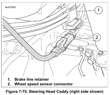
2. See Figure 7-75. Separate sensor connector (2). Remove sensor cable from caddy.
3. Release sensor cable from conduit clips and cut cable straps securing cable to brake hoses.
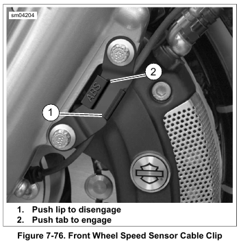
4. See Figure 7-76. Release sensor cable from clip at caliper:
a. Push on lip (1) at rear of clip to disengage from bracket. Rotate tab (2) (stamped ABS) rearward until clip is perpendicular to bracket and remove cable.
b. Rotate tab (2) forward until clip is aligned with bracket and apply pressure to tab until lip (1) engages.
5. Retract axle until front WSS is free. See 2.4 FRONT WHEEL.
NOTE
The WSS works in conjunction with the ABS encoder bearing installed in the wheel hub. If necessary, see 2.10 SEALED WHEEL BEARINGS for bearing removal and installation instructions.
Installation
NOTE
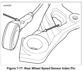
Install WSS with index pin on the outboard side.
1. Push axle through new front WSS and left fork slider.
2. Secure front wheel. See 2.4 FRONT WHEEL. Rotate WSS until it makes contact with fork slider. Back off just enough to maintain clearance between the WSS wire stem and fork slider.
3. Route sensor cable up to lower fork bracket following brake hose.
4. Route connector up through opening in lower fork bracket.
5. Frame mounted fairing models: Route cable between the upper and lower legs of inner fairing mounting bracket to the right steering head caddy.
6. Continue to right steering head caddy. Mate connector and secure cable to caddy.
7. Secure the sensor cable and fender tip lamp wires using three new cable straps:
a. On the brake hose lower crimp capturing WSS cable and brake hose.
b. Midway between the upper and lower brake hose crimps capturing WSS cable, brake hose and front fender tip lamp wires, if equipped.
c. On upper crimp capturing WSS cable, brake hose and front fender tip lamp wires, if equipped.
8. See Figure 7-76. Install WSS cable in retaining clip:
a. Push on lip (1) at rear of retaining clip to disengage from bracket. Rotate tab (2) (stamped ABS) rearward until retaining clip is perpendicular to bracket. Install cable.
b. Rotate tab (2) forward and apply pressure until lip (1) engages. Gently tug on cable to verify that retaining clip is properly installed.
9. Fork mounted fairing models: Capture WSS cable to three retainers on brake hoses near steering head. Install outer fairing. See 2.37 OUTER FAIRING AND WINDSHIELD: FORK MOUNTED FAIRING MODELS.