Removal: Flat Lens Style
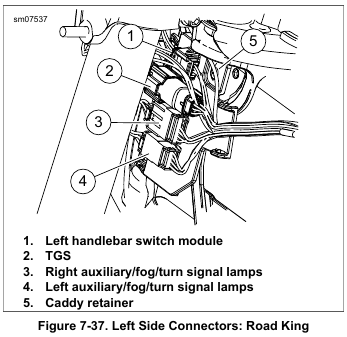
1. See Figure 7-37. Remove headlamp assembly. See 7.9 HEADLAMP. Disconnect front turn signal lamps connector.
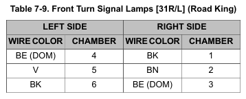
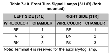
2. Remove terminals from connector housing. Refer to Table 7-9 or Table 7-10. See A.17 JAE MX19 SEALED CONNECTORS.
3. See Figure 7-36. Remove two screws to release turn signal lamp from mounting bracket.
NOTE
Make sure that chaser wire is of sufficient strength to pull terminals through conduit without breaking. Wire lengths must also be long enough that free ends are not lost in conduit when pulled.
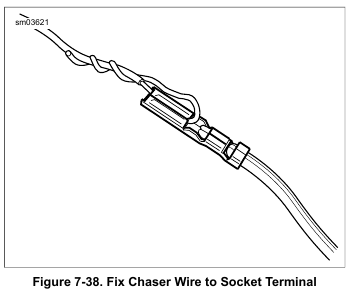
4. See Figure 7-38. Obtain three equal lengths of strong flexible wire for use as chaser wires. Securely attach a chaser wire to terminal of each wire.
5. Carefully pull wires to draw terminals through both sections of conduit. For best results, pull one wire at a time.
6. Remove chaser wire from terminals.
Installation: Flat Lens Style
1. Lay old turn signal lamp next to new turn signal lamp and cut wires to length.
2. Strip 3/16 in (4.8 mm) of insulation off wires and crimp on new terminals. See A.17 JAE MX19 SEALED CONNECTORS.
3. Secure chaser wires to terminals. Carefully draw terminals back through conduit.
4. Remove chaser wires.
5. Install terminals into connector housing. Refer to Table 7-9 or Table 7-10. See A.17 JAE MX19 SEALED CONNECTORS.
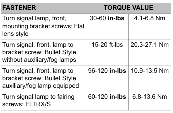
6. See Figure 7-36. Start two screws to secure turn signal lamp to mounting bracket. Verify that conduit fits in slot at back of bracket and is not pinched. Tighten screws to 30-60 in-lbs (4.1-6.8 Nm).
7. Connect front turn signal/auxiliary/fog lamp connector.
8. See Figure 7-37. Secure anchor to fork stem nut lockplate.
Install headlamp assembly. See 7.9 HEADLAMP.
Be sure that all lights and switches operate properly before operating motorcycle. Low visibility of rider can result in death or serious injury. (00316a)
9. Check operation of all lamps.
Removal: Bullet Style, Fork Mounted
1. Remove turn signal/auxiliary/fog lamp bracket. See 7.10 AUXILIARY/FOG LAMPS AND BRACKETS.
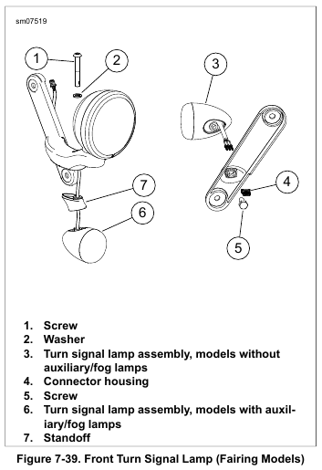
2. See Figure 7-39. Remove terminals from connector housing (4). See A.17 JAE MX19 SEALED CONNECTORS.
3. Remove screw (1 or 5). Remove lamp assembly from bracket.
4. Remove reflector assembly:
a. Separate mounting bracket from harness.
b. Remove lens and bulb.
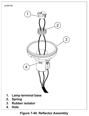
c. See Figure 7-40. Insert a right angle pick or a small hex key from inside the bulb socket through hole (4). Pull reflector from lamp.
d. Remove rubber isolator (3).
Installation: Bullet Style, Fork Mounted
1. Install reflector assembly:
a. Seat reflector assembly in rubber isolator, aligning tab on reflector with slot in isolator.
b. Feed wires through lens opening and out through unthreaded hole.
c. Aligning tab on reflector with slot inside lamp, use thumbs of both hands and apply even pressure around outer edge of reflector assembly until fully seated.
d. Liberally apply dielectric grease to contacts in socket and at bottom of bulb. Install bulb and lens with slot at bottom of lamp.
e. Feed wires through hole in mounting bracket.
2. See Figure 7-39. Install lamp on mounting bracket. Tighten to:
a. Models without auxiliary/fog lamps: 15-20 ft-lbs (20.3-27.1 Nm).
b. Models with auxiliary/fog lamps: 96-120 in-lbs (10.9-13.5 Nm).
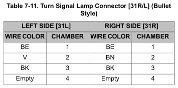
3. Install terminals into connector housing as shown in Table 7-11. See A.17 JAE MX19 SEALED CONNECTORS.
4. Install turn signal/auxiliary/fog lamp bracket. See 7.10 AUXILIARY/FOG LAMPS AND BRACKETS.
Be sure that all lights and switches operate properly before operating motorcycle. Low visibility of rider can result in death or serious injury. (00316a)
5. Check operation of all lamps.
Removal: Bullet Style, Fairing Mounted
1. Remove outer fairing. See 2.42 OUTER FAIRING AND WINDSHIELD: FRAME MOUNTED FAIRING MODELS.
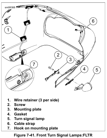
2. See Figure 7-41. Cut cable strap (6). Remove wire retainers (1). Release wires from hook (7).
3. Remove screw (2), mounting plate (3), gasket (4) and lamp (5).
4. To remove reflector/isolator assembly:
a. Remove terminals from connector housing. See A.17 JAE MX19 SEALED CONNECTORS.
b. Separate lamp from mounting bracket.
c. Remove lens and bulb.
d. See Figure 7-40. Insert a right angle pick or a 7/64 in hex key through hole (4) and pull reflector from lamp.
e. Remove isolator (3) from lamp if still installed.
Installation: Bullet Style, Fairing Mounted
1. Assemble front turn signal lamp:
a. Seat reflector assembly in rubber isolator, aligning tab on reflector with slot in isolator.
b. Feed wires through lens opening and out through non-threaded hole.
c. Aligning tab on reflector with slot inside lamp, use thumbs of both hands and apply even pressure around outer edge of reflector assembly until fully seated.
d. Liberally apply dielectric grease to contacts in socket and at bottom of bulb. Install bulb and lens with slot at bottom of lamp.
e. Install lamp onto mounting bracket.
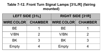
f. Install terminals into connector housing as shown in Table 7-12. See A.17 JAE MX19 SEALED CONNECTORS.
2. See Figure 7-41. Install mounting plate (3), gasket (4) and lamp (5). Secure with screw (2). Tighten to 60-120 in-lbs (6.8-13.6 Nm).
3. Secure harness in hook (7) and route upwards.
4. Clean all residual adhesive from retainer mounting areas.
NOTE
Place retainers (1) within bosses molded into the inside of the fairing.
5. Secure with three new wire retainers (1) and cable strap (6).
6. Install outer fairing. See 2.42 OUTER FAIRING AND WINDSHIELD: FRAME MOUNTED FAIRING MODELS.
Be sure that all lights and switches operate properly before operating motorcycle. Low visibility of rider can result in death or serious injury. (00316a)
7. Check operation of all lamps.