
Removal: All but FLHX/S, FLTRX/S
1. Remove saddlebag as necessary. See 2.31 SADDLEBAGS.
2. See Figure 7-42. Remove and disconnect tail lamp assembly from chrome base.

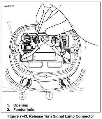
3. See Figure 7-43. Disconnect turn signal lamp connector (2-place Multilock). Use a pick or small screwdriver to press latch.
4. Feed connector to inboard side of rear fender.
5. Release harness from cable clip inside fender.
6. Draw out harness and connector through fender hole (2).
7. Draw connector through channel on inboard side of rear turn signal lamp bracket, so that length of conduit hangs below turn signal lamp.
8. Remove two screws to release turn signal lamp assembly.
Use a LONG SHANK BALL END SOCKET (Part No. Snapon FABL5) or equivalent through the channel in the bracket.
9. Remove terminals from connector. See A.21 TYCO 070 MULTILOCK UNSEALED CONNECTOR.
Installation:All but FLHX/S, FLTRX/S
1. Place new turn signal lamp assembly next to discarded unit and cut wires to proper length.
2. Crimp new terminals onto turn signal lamp wires. Install terminals into connector housing. Refer to Table 7-13. See A.21 TYCO 070 MULTILOCK UNSEALED CONNECTOR.

3. Install turn signal lamp assembly. Tighten to 30-50 in-lbs (3.4-5.6 Nm).
4. See Figure 7-43. Route connector through channel in bracket, then through fender hole (2).
5. Capture harness in cable clip under fender.
6. Feed connector through opening (1) in chrome base.
7. See Figure 7-42. Connect turn signal harness connector (1 or 2).
8. Connect tail lamp connector (3). Verify that tail lamp harness is positioned outboard of the rear fender tip lamp and left turn signal lamp harnesses.
9. Install tail lamp. Tighten to 20-24 in-lbs (2.3-2.7 Nm).
Be sure that all lights and switches operate properly before operating motorcycle. Low visibility of rider can result in death or serious injury. (00316a)
10. Test lamp operation.
11. Install saddlebag.
Removal: FLHX/S, FLTRX/S
NOTES
• This procedure covers replacement of the rear turn signal lamp reflector/ isolator assembly only.
• Individual LEDs cannot be replaced. Replace assembly upon failure. See 7.14 TURN SIGNAL LAMPS, Rear Turn Signal Lamps Bracket.
1. Models with tail lamp:
a. Remove circuit board and chrome base. See 7.11 REAR LIGHTING.
b. Remove terminals from turn signal lamp connector housing. See A.21 TYCO 070 MULTILOCK UNSEALED CONNECTOR.
c. Release harness from cable clip inside fender.
d. Draw harness and terminals through hole to outboard side of fender. Proceed with reflector/isolator removal.
2. Models without tail lamp:
a. Remove turn signal lamps bracket. See 7.14 TURN SIGNAL LAMPS, Rear Turn Signal Lamps Bracket.
b. Remove grommet from harness.
c. Remove license plate bracket.
d. Remove screws securing license plate lamp.
e. Remove terminals from connector housing. See A.11 DELPHI MICRO 64 SEALED CONNECTORS.
f. Pull wires through main conduit.
Installation: FLHX/S, FLTRX/S
1. Models with tail lamp:
a. Install new terminals onto wires. See A.21 TYCO 070 MULTILOCK UNSEALED CONNECTOR.
b. Feed terminals through hole to inboard side of fender.
c. Install terminals into connector housing. Refer to Table 7-13. See A.21 TYCO 070 MULTILOCK UNSEALED CONNECTOR.
d. Capture harness in cable clip inside fender.
e. Install chrome base and circuit board assembly. See 7.11 REAR LIGHTING.
2. Models without tail lamp:
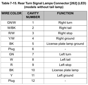
a. Feed wires through main conduit. Install new terminals and install in connector housing. Refer to Table 7-14 or Table 7-15. See A.11 DELPHI MICRO 64 SEALED CONNECTORS.
b. Route both turn signal lamp harnesses under license plate lamp area. Install license plate lamp and license plate bracket. See 7.14 TURN SIGNAL LAMPS, Rear Turn Signal Lamps Bracket.
c. Install turn signal lamps bracket. See 7.14 TURN SIGNAL LAMPS, Rear Turn Signal Lamps Bracket.
Be sure that all lights and switches operate properly before operating motorcycle. Low visibility of rider can result in death or serious injury. (00316a)
3. Test lamp operation.

Lamp Repair
NOTE
LED type lamps are not serviced separately. Replace the light bar assembly.
1. Remove lens and bulb.
2. Push grommet into lamp housing. Lubricate grommet with glass cleaner, if necessary.
3. See Figure 7-44. Insert a right angle pick or a small hex key from inside the bulb socket through hole (4). Pull reflector from lamp.
4. Remove rubber isolator (3).
5. Install rubber isolator.
6. Place new reflector assembly next to discarded unit and cut wires to proper length.
7. Seat reflector assembly in rubber isolator, aligning tab on reflector with slot in isolator.
8. Feed wires through lens opening and out through hole in lamp housing.
9. Install grommet in lamp housing. Lubricate grommet with glass cleaner, if necessary.
10. Align tab on reflector with slot inside lamp. Use thumbs of both hands to apply even pressure around outer edge of reflector assembly until fully seated.
11. Liberally apply dielectric grease to contacts in socket and at bottom of bulb. Install bulb and lens with slot at bottom of lamp.

Leave a Reply