1. Check inside of rotor and remove any metal fragments captured by magnets.
2. Clean the rotor using a petroleum solvent. Clean the stator and grommet by wiping it with a clean cloth.
1. Check inside of rotor and remove any metal fragments captured by magnets.
2. Clean the rotor using a petroleum solvent. Clean the stator and grommet by wiping it with a clean cloth.
1. Remove seat. See 2.30 SEAT.
To prevent accidental vehicle start-up, which could cause death or serious injury, disconnect negative (-) battery cable before proceeding. (00048a)
2. Remove battery negative cable (black) from battery.
3. Remove the primary chaincase. See 5.5 PRIMARY CHAINCASE HOUSING.
The high-output rotor contains powerful magnets. Exercise caution to prevent possible hand injury during removal and installation. (00558b)
4. Disconnect stator connector from voltage regulator. See 7.20 VOLTAGE REGULATOR.
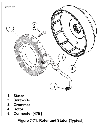
5. See Figure 7-71. Remove alternator rotor (4). Use two bolts inserted through the holes in the rotor face to aid during removal.
6. Cut anchored cable strap securing stator wiring to frame.
NOTE
The rubber molded stator connector is not serviceable. Replace parts as necessary.
7. Remove four screws to free stator from crankcase. Discard screws.
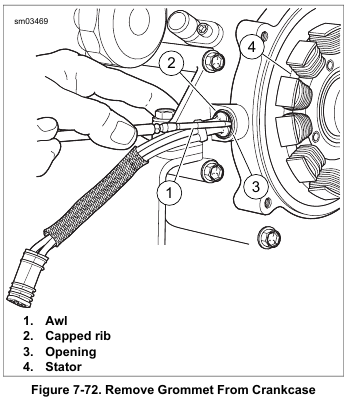
8. See Figure 7-72. Using point of awl or small screwdriver, carefully move grommet away from crankcase and squirt isopropyl alcohol or glass cleaner into opening. Repeat this step at one or two other locations around grommet.
9. Push on the grommet from outside of crankcase while pulling through the bore with needle nose pliers. Do not pull on the wires unless the stator will be replaced. Exercise caution to avoid damaging ribs on grommet if stator is to be reused.
10. Draw conduit and connector through crankcase bore as stator is removed.
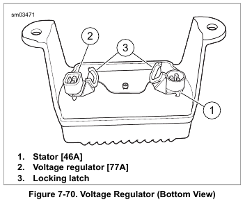
1. See Figure 7-70. Install stator connector [46] (1). Secure connector with locking latch (3).
2. Install voltage regulator connector [77] (2). Secure connector with locking latch (3).
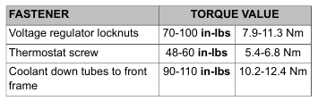
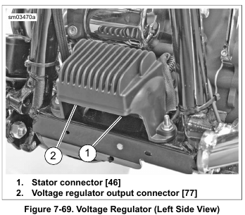
3. See Figure 7-69. Install voltage regulator with locknuts on studs. Tighten to 70-100 in-lbs (7.9-11.3 Nm).
4. Verify that wires are properly secured.
5. Twin-Cooled models:
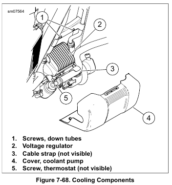
a. See Figure 7-68. Install screw (5) securing thermostat.
Tighten to 48-60 in-lbs (5.4-6.8 Nm).
b. Install screws (1) securing coolant down tubes.
Tighten to 90-110 in-lbs (10.2-12.4 Nm).
c. Install new cable strap (3). Install coolant pump cover (4).
6. Install main fuse. See 7.3 SYSTEM FUSES AND RELAYS.
7. Verify charging system operation.
1. Remove main fuse. See 7.3 SYSTEM FUSES AND RELAYS.
2. Twin-Cooled models:
a. See Figure 7-68. Remove coolant pump cover (4).
Cut cable strap (3).
b. Remove screws (1) securing coolant downtubes.
c. Remove screw (5) securing thermostat.
d. Pull down tube assembly away from frame to access nut securing voltage regulator.
3. Remove regulator from lower frame:
a. Remove locknuts from studs on lower frame crossmember.
b. Lift voltage regulator off studs. Allow voltage regulator to hang upside down at front of lower frame crossmember.
4. See Figure 7-70. Release locking latch. Remove voltage regulator connector [77] (2).
5. Release locking latch. Remove stator connector [46] (1).

1. Verify that the copper seal washer is in place on the ACR.
2. See Figure 7-65. Identify a location around the threads of the ACR approximately 1/3 of the way up from the end.
3. See Figure 7-66. Apply three equally spaced dots of LOCTITE 246 MEDIUM STRENGTH/HIGH TEMPERATURE THREADLOCKER (blue) on threads.
4. To prevent cross threading, install and finger tighten.
5. See Figure 7-67. Using ACR SOLENOID SOCKET (Part No. HD-48498-A), tighten to 13-17 ft-lbs (17.6-23.0 Nm).
6. Route the wire harness between the cylinders.
7. Install rocker box and rocker cover. See 3.25 TOP END OVERHAUL: ASSEMBLY.
8. Mate the ACR connectors [203R] and [203F] to the main wiring harness. Secure connectors to retaining clip.


1. Remove the rocker cover and the rocker box. See 3.18 TOP END OVERHAUL: DISASSEMBLY.
2. Separate the ACR rear [203R] or front [203F] connector from the main wiring harness and remove connectors from retainer clip.
3. See Figure 7-67. Use ACR SOLENOID SOCKET (Part No. HD-48498-A) to remove the ACR from the cylinder head.


NOTES
• ACR is used only on 103 cu. in. and larger engines.
• See Figure 7-61. The tip of ACR solenoids for Twin-Cooled engines are approximately 0.500 in (13 mm) longer than those for air-cooled engines. Twin-Cooled ACR’s will contact the pistons of an air-cooled engine.
See Figure 7-62. The ACR is opened and closed by the ECM to assist starting.
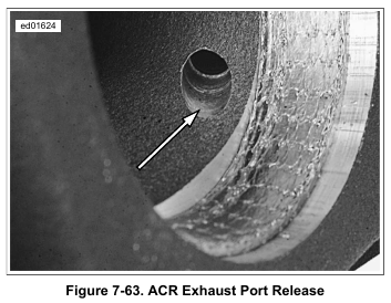
See Figure 7-63. When open, compressed gases are released through the exhaust port.
Twin-Cooled models: ACR service requires the removal and installation of the upper coolant hoses to access the rocker covers. See C.5 COOLING SYSTEM REPAIR, Upper Coolant Line Removal.


1. Hand start new ET sensor into bore at back of front cylinder.
2. Tighten to 120-180 in-lbs (13.6-20.3 Nm).
3. Install ET sensor connector [90]. Pull boot over connector.
4. Install main fuse. See 7.3 SYSTEM FUSES AND RELAYS.
1. Remove main fuse. See 7.3 SYSTEM FUSES AND RELAYS.
2. Loosen horn bracket bolt to front cylinder head. Remove horn bracket bolt (with flat washer) from rear cylinder head and swing horn bracket forward.
3. Pull back boot at back of front cylinder and remove ET sensor connector [90].
4. See Figure 7-60. Remove sensor.


1. Install new O-ring on sensor body if damaged. Apply a thin film of clean engine oil to O-ring before installation.
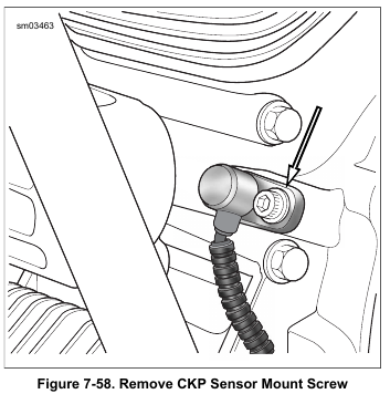
2. See Figure 7-58. Secure sensor with screw. Tighten to 100-120 in-lbs (11.3-13.6 Nm).
3. Route connector and convoluted tubing downward at rear of front engine stabilizer link to front caddy at bottom of lower frame crossmember.
4. Mate connector [79].

5. Mount connector to caddy T-stud.
6. Install main fuse. See 7.3 SYSTEM FUSES AND RELAYS.