Removal
1. Remove main fuse. See 7.3 SYSTEM FUSES AND RELAYS.
2. Remove the ignition switch knob:
a. Insert the ignition switch key and turn to the UNLOCK position. Leave the key installed.
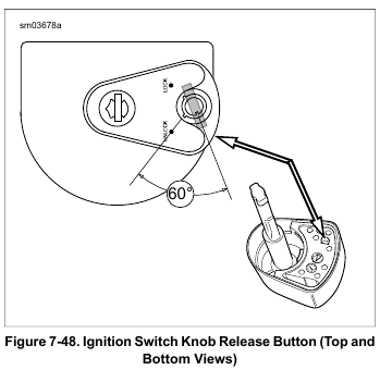
b. See Figure 7-48. Rotate the knob to FORK LOCK.
c. Press and hold the release button at bottom (left side) of the knob, and turn key 60 degrees counterclockwise.
d. Lift knob to remove. Spring will drop out of bore at underside of knob when removed.
NOTE
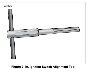
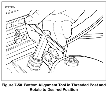
See Figure 7-50. Use IGNITION SWITCH ALIGNMENT TOOL (Part No. HD-51198) to move the switch to other positions as required. Insert tool until bottom of handle contacts top of ignition switch. Rotate handle to the selected position.
3. Fork mounted fairing models:
a. Remove nut and collar from ignition switch.
b. Remove dash panel. See 2.38 DASH PANEL: FORK MOUNTED FAIRING MODELS.
4. Frame mounted fairing models: Remove instrument bezel. See 2.40 INSTRUMENT BEZEL: FRAME MOUNTED FAIRING MODELS.
5. Disconnect ignition switch connector [33].
6. Domestic models: Remove two screws and flat washers securing ignition switch assembly.
Always wear proper eye protection when drilling or grinding. Flying debris could cause serious eye injury. (00402e)
7. HDI models: Remove two break-away screws:
a. Rotate inner fairing to access screws. See 7.3 SYSTEM FUSES AND RELAYS.
b. Use a center punch to make a pilot hole at the top of each break-away screw.
c. Use a 1/8 inch left handed bit in drill. Set the drill to REVERSE and use to spin out the screws.
NOTE
If the above method fails, use a 3/16 inch bit to drill off heads of the screws to remove switch. Use pliers to remove remainder of screws from upper fork bracket.
8. Remove ignition switch.
Installation
1. Place ignition switch into position.
2. Domestic models: Install two screws and flat washers.
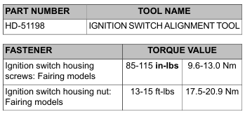
Tighten to 85-115 in-lbs (9.6-13.0 Nm).
3. HDI models:
a. Verify that the threads in the upper fork bracket are clean and in good condition. Dirty and/or damaged threads may cause the heads of the break-away screws to snap off before the switch housing is properly tightened.
NOTE
Use care to avoid losing heads of break-away screws in motorcycle. Vibration may cause captured heads to scratch finished surfaces, chafe wires or cause other damage.
b. Install two new break-away screws and flat washers.
Tighten until heads snap off.
c. Rotate inner fairing into position and secure. See 7.3 SYSTEM FUSES AND RELAYS.
4. Install ignition switch connector.
5. Fork mounted fairing models:
a. Install dash panel. See 2.38 DASH PANEL: FORK MOUNTED FAIRING MODELS.
b. Install collar and nut. Tighten to 13-15 ft-lbs (17.5-20.9 Nm).
6. Frame mounted fairing models: Install instrument bezel.
See 2.40 INSTRUMENT BEZEL: FRAME MOUNTED FAIRING MODELS.
7. Place spring into bore at underside of knob.
8. Install ignition switch knob:
a. See Figure 7-48. Verify that button at bottom of knob is pressed and key is turned 60 degrees counterclockwise of the UNLOCK position.
b. With the knob pointing toward the FORK LOCK posi-
tion, insert shaft into ignition switch.
c. Hold the knob down and the turn key clockwise to the
UNLOCK position. An audible “click” is heard when
knob and switch are properly engaged.
d. Release the knob. Rotate through all four switch
positions to verify proper operation. If knob does not
install properly, proceed to next step.
9. Knob was removed in the ACCESS position or switch was moved out of the FORK LOCK position:
a. See Figure 7-50. Insert alignment tool until bottom of handle contacts top of ignition switch. While holding front forks at the left fork stop, rotate handle of tool counterclockwise until fork locks.
b. Remove tool. Install knob.
c. If knob does not install properly, proceed to next step.
10. Detent and switch position lugs are misaligned:
a. Insert knob into ignition switch and rotate until it drops into the partially installed position. Take note whether it is pointing toward the rear, or to ACCESS, IGNITION or OFF.
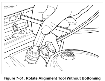
b. See Figure 7-51. Remove knob. Insert and hold alignment tool so that the bottom of the handle is approximately 0.50-0.75 in (12.7-19.1 mm) from the top of the ignition switch.
c. Rotate alignment tool counterclockwise the number of positions needed to get to FORK LOCK.
d. Install knob.
11. Install main fuse. See 7.3 SYSTEM FUSES AND RELAYS.
Leave a Reply