Author: Sam

  • 2015 Touring – ANTENNA CABLES – REMOVAL

    Main Cable

    NOTES
    • Replacement of the radio and CB antenna cables is basically the same.
    • Most of the original cable will remain within the main harness conduit.
    1. Remove seat and fuel tank. See 4.6 FUEL TANK.

    2. Remove outer fairing. See 2.37 OUTER FAIRING AND WINDSHIELD: FORK MOUNTED FAIRING MODELS.

    3. See Figure 7-101. Disconnect antenna cable from radio.
    Cut cable where it exits front and rear of the main harness.

    4. Remove wire trough cover.

    5. See Figure 7-102. Disconnect antenna cable connector at rear fender

    6. Cut cable strap (3). Remove antenna cable.

    Cable Extension: Models with Tour-Pak

    1. Remove Tour-Pak harness. See 7.13 TOUR-PAK LIGHTS, Tour-Pak Lights Harness.

    2. See Figure 7-104. Cut cable strap (2). Peel away the forward wrap (3).

    3. CB antenna cable (6):
    a. Remove tape (5) securing cable to harness.
    b. Remove antenna cable.

    4. Radio antenna cable (7):
    a. Cut antenna cable extension where it exits each end of harness wrap.
    b. Remove antenna cable.

    Cable Extension: FLHX/S, FLTRX/S

    1. Remove left saddlebag.

    2. See Figure 7-103. Release antenna cable from three upper clips (1).

    3. Disconnect antenna cable from antenna.

    4. See Figure 7-105. Disconnect antenna cable connector (1). Remove cable.


  • 2015 Touring – BOOM! BOX INFOTAINMENT SYSTEM – RIDER HEADSET CONNECTOR

    Removal

    1. Remove console. See 4.6 FUEL TANK, Console.

    2. Using DIN CONNECTOR TOOL (Part No. HD-51656), rotate lock ring counterclockwise to loosen.

    3. Remove lock ring and cap.

    4. Remove headset connector and harness assembly.

    Installation

    1. Insert headset connector through hole in console.

    2. Slide weather cap over headset connector.

    3. With the notches on the outboard side, thread lock ring onto headset connector.

    4. Using DIN CONNECTOR TOOL (Part No. HD-51656), tighten to 7-9 in-lbs (0.8-1.0 Nm).

    5. Install console on fuel tank capturing wire harness and front headset connector harnesses in metal clips. See 4.6 FUEL TANK, Console.

    6. Test operation of headset connector.


  • 2015 Touring – BOOM! BOX INFOTAINMENT SYSTEM – REAR SPEAKER ENCLOSURES

    Removal

    NOTE

    It is not necessary to remove the enclosure to service the internal components.

    1. Remove Tour-Pak liner. See 2.34 TOUR-PAK SERVICE, Tour-Pak Liner.
    2. See Figure 7-98. Separate rear audio connector from main harness.

    NOTE

    If both speaker enclosures are removed, connector disassembly is not required.

    3. Remove appropriate terminals from housing. Refer to Table 7-18.

    NOTE

    See Figure 7-99. Screws securing right speaker enclosure also secure power outlet (4).

    4. Remove three screws (6) with flat washers (5) to free speaker enclosure from Tour-Pak.

    5. Remove gasket (2) and sound port (3).

    Installation

    1. See Figure 7-99. Install sound port and new gasket (2).

    2. Install three screws with flat washers to secure speaker enclosure, sound port and power outlet (right side only) to Tour-Pak. Tighten to 20-25 in-lbs (2.3-2.8 Nm).

    3. Install terminals in connector housing. Refer to Table 7-18 for cavity assignments.

    4. Mate rear audio connector to main harness.

    5. Install Tour-Pak liner. See 2.34 TOUR-PAK SERVICE, Tour-Pak Liner.

    Disassembly

    1. See Figure 7-100. Remove four screws (4).

    2. Remove speaker and grille from enclosure. Disconnect terminals.

    3. Right speaker:
    a. Remove well nut (2) to access switch screw.
    b. Remove screws securing switch assembly.
    c. Remove harness and switch assembly.
    d. Remove switch bezel.

    NOTE

    It is not necessary to remove the enclosure to service the rear speaker components.

    4. Left speaker:
    a. Using DIN CONNECTOR TOOL (Part No. HD-51656), remove nut and weather cap from passenger headset connector.
    b. Remove passenger headset connector and harness assembly.

    5. See Figure 7-99. To separate left and right harnesses, remove terminals from connector (7).

    6. Remove harness grommet.

    Assembly

    1. Install harness grommet. The left enclosure grommet has the larger hole.

    2. See Figure 7-99. If separated, assemble left and right harnesses to connector (7). Refer to Table 7-18 for cavity assignments.

    3. Right speaker:
    a. Install switch bezel.
    b. Install harness and switch assembly with wires nearest to wall of speaker enclosure.
    c. Install screws securing switch assembly. Tighten to 25-30 in-lbs (2.8-3.4 Nm).
    d. Install well nut removed to access screw.
    e. Route harness through grommet.

    4. Left speaker:
    a. Install passenger headset connector and harness assembly.
    b. Install weather cap and nut to secure passenger headset connector. Using DIN CONNECTOR TOOL (Part No. HD-51656), tighten to 7-9 in-lbs (0.8-1.0 Nm).
    c. Route harness under boss and through grommet.

    5. See Figure 7-100. Install cable strap on harness next to inside of grommet (6) to act as strain relief.

    6. Connect terminals to speaker.

    NOTE

    Over-tightening screws (4) can cause well nuts to pull through mounting holes.

    7. Secure speaker and grille with four screws (4). Tighten carefully.


  • 2015 Touring – BOOM! BOX INFOTAINMENT SYSTEM – FRONT FAIRING SPEAKER AND ENCLOSURE: FRAME MOUNTED FAIRING

    NOTES

    • Repair of the left and right sides are similar.
    • Speaker enclosure removal and installation does not require speaker removal.

    Speaker Grille

    NOTE

    Do not damage speaker when inserting right angle tool.

    1. See Figure 7-95. Remove speaker grille.
    Method A:
    a. Carefully insert a right angle tool (3) through a hole in the grille next to one retainer (1).
    b. Pull to release retainer.
    c. Repeat with remaining retainer.
    d. Remove speaker grille.

    2. Method B:
    a. Remove top air duct.
    b. From above, reach down into speaker area. Push on tab to disengage upper retainer (1).
    c. Carefully pull near lower retainer (1) to disengage.
    Remove grille.

    3. See Figure 7-96. Install speaker grille:
    a. Verify rubber gasket is in place on perimeter of grille.
    b. Engage tab (2) into grille opening.
    c. Engage retainers (1) in slots.
    d. Push on grille in retainer areas until an audible click is heard.
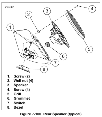
    Speaker Only

    1. Remove speaker grille.
    2. Remove screws securing speaker to enclosure.
    3. Hold speaker away from enclosure and disconnect wires.
    Remove speaker.

    NOTE

    Verify that hole in speaker frame mates with alignment pin on enclosure.

    4. Connect wires to speaker terminals. Set speaker in place.

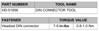
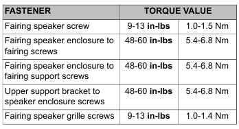
    5. Secure with four screws. Tighten to 9-13 in-lbs (1.0-1.5 Nm).

    6. Install speaker grille.

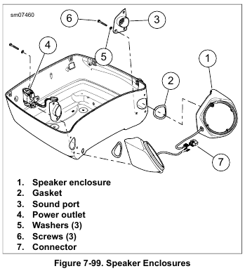
    Speaker Enclosure Removal

    NOTE

    Never operate vehicle with the speaker enclosures removed.
    These components provide important structural support to the inner fairing. Operating without these components can result in damage to fairing assembly.

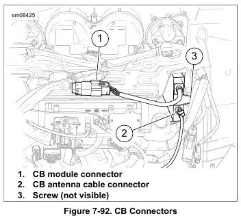
    1. See Figure 7-97. Disconnect speaker connector (2).

    2. Left side: Remove power outlet cable from features on enclosure.

    3. Right side: Separate USB cable anchor (6) from tab (5) at upper corner of enclosure.

    NOTE

    Do not remove the Torx head screws securing the speaker enclosure halves together.

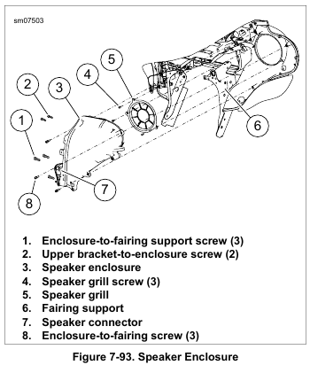
    4. Remove three socket head screws (3) securing lower enclosure.

    5. Remove two socket head screws (1) securing enclosure to support bracket.

    6. Remove speaker enclosure (4) from fairing.

    NOTE

    Do not disassemble speaker enclosure.

    7. Remove four screws to free speaker from enclosure.

    8. Disconnect wires. Remove speaker from enclosure.

    9. If necessary, remove grommet and harness.

    Speaker Enclosure Installation

    NOTE

    Verify that the harness grommet is correctly installed. An incorrectly installed grommet can result in poor audio, whistling or a rattle.

    1. If removed, install harness and grommet.

    2. Attach speaker wire connectors.

    NOTE

    Align hole in speaker frame with alignment pin on enclosure.

    3. Install speaker. Secure with four screws. Tighten to 9-13 in-lbs (1.0-1.5 Nm).

    4. See Figure 7-97. Install speaker enclosure (4) to inner fairing. Start all screws (1, 3).

    5. Tighten two screws (1) to 48-60 in-lbs (5.4-6.8 Nm).

    6. Tighten screws (3) to 48-60 in-lbs (5.4-6.8 Nm) ending with the screw nearest the rear.

    7. Secure harness to speaker enclosure.

    8. Install outer fairing. See 2.42 OUTER FAIRING AND WINDSHIELD: FRAME MOUNTED FAIRING MODELS.


  • 2015 Touring – BOOM! BOX INFOTAINMENT SYSTEM – RADIO: FRAME MOUNTED FAIRING

    Removal

    NOTE

    Never operate vehicle with the radio or upper support bracket removed. These components provide important structural support to the fairing. Damage to the fairing assembly can result if operated without these components installed.

    1. Remove main fuse. See 7.3 SYSTEM FUSES AND RELAYS.

    2. Remove outer fairing. See 2.42 OUTER FAIRING AND WINDSHIELD: FRAME MOUNTED FAIRING MODELS.

    NOTE

    Some connectors are not used on all models.

    3. See Figure 7-94. Disconnect:
    a. Radio harness connector (6).
    b. USB connector (5).
    c. AM/FM antenna cable connector (4).
    d. GPS connector (3).
    e. SiriusXM connector (2) (if equipped)

    4. Remove four screws (1) to release radio from fairing support bracket.

    5. Pull radio up and forward to remove.

    NOTE

    The XM module is very fragile and is sensitive to static discharge.

    6. XM equipped:
    a. Remove screws securing XM module in radio frame.
    b. Transfer XM module into new radio immediately. If new radio is not available, place XM module in a static proof bag and store in a safe place.
    c. Tighten screw securely.

    Installation

    1. Position radio on fairing support bracket and push toward opening in inner fairing.

    2. See Figure 7-94. Install four screws (1). Tighten to 60-84 in-lbs (6.8-9.5 Nm).

    NOTE

    Some connectors are not used on all models.

    3. Mate connectors:
    a. Radio harness connector (6).
    b. USB connector (5).
    c. AM/FM antenna cable connector (4).
    d. GPS connector (3).
    e. SiriusXM connector (2) (if equipped).

    4. Install fairing vent and outer fairing. See 2.42 OUTER FAIRING AND WINDSHIELD: FRAME MOUNTED FAIRING MODELS.

    5. Install main fuse. See 7.3 SYSTEM FUSES AND RELAYS.

    6. If installing a new radio, it must be set up using DIGITAL TECHNICIAN II (Part No. HD-48650):
    a.Choose the REFLASH icon.
    b. Follow the on-screen prompts. If the vehicle has an amplifier, it must also be configured after configuring the radio.

    NOTE

    Instructions to check, download and install software are available in PDF format at www.harley-davidson.com/softwaredownloads.

    7. Check software version:
    a. Visit www.harley-davidson.com/softwaredownloads.
    b. Compare the software version number to the online version number.
    c. If the online version number is higher than the displayed version number, download and install the latest version.


  • 2015 Touring – BOOM! BOX INFOTAINMENT SYSTEM – FRONT FAIRING SPEAKERS: FORK MOUNTED FAIRING

    Removal

    NOTE

    Never operate vehicle with the speaker enclosures removed. These components provide important structural support to the fairing. Operating without these components can result in damage to fairing assembly.

    1. Remove outer fairing. See 2.37 OUTER FAIRING AND WINDSHIELD: FORK MOUNTED FAIRING MODELS.

    2. Remove harness anchors from speaker enclosure.

    3. See Figure 7-93. Disconnect speaker connector (7).

    4. Right side: Disconnect power outlet connector.

    5. Left side: Remove CB module if equipped. See 7.32 BOOM! BOX INFOTAINMENT SYSTEM, CB Module: Fork Mounted Fairing.

    6. Remove three screws (1) securing enclosure to fairing support (6).

    7. Remove two screws (2) securing enclosure to upper support bracket.

    8. Remove three screws (8). Remove speaker enclosure from fairing.

    NOTE

    Do not remove screws securing speaker enclosure halves together.

    9. Remove four screws to free speaker from enclosure.

    10. Disconnect wires and remove speaker from enclosure.

    11. If necessary, remove grommet and harness.

    Installation

    NOTE

    Verify that harness grommet is correctly installed. An incorrectly installed grommet can result in poor audio, whistling or a rattle.

    1. If removed, install harness and grommet.

    2. Attach speaker wire connectors.

    NOTE

    Verify hole in speaker frame mates with alignment pin on enclosure.

    3. Install speaker and secure with four screws. Tighten to 9-13 in-lbs (1.0-1.5 Nm).

    4. See Figure 7-93. Install speaker enclosure to inner fairing.
    Secure with three screws (8). Tighten to 48-60 in-lbs (5.4-6.8 Nm).

    5. Secure enclosure to fairing support (6) with three screws (1). Tighten to 48-60 in-lbs (5.4-6.8 Nm).

    6. Secure enclosure to upper support bracket with two screws (2). Tighten to 48-60 in-lbs (5.4-6.8 Nm).

    7. Mate speaker and power outlet connectors. Secure harness anchors to speaker enclosure.

    8. Install CB module if equipped. See 7.32 BOOM! BOX INFOTAINMENT SYSTEM, CB Module: Fork Mounted Fairing.

    9. Install outer fairing. See 2.37 OUTER FAIRING AND WINDSHIELD: FORK MOUNTED FAIRING MODELS.

    Speaker Grille

    1. Remove speaker enclosure. See 7.32 BOOM! BOX INFOTAINMENT SYSTEM, Front Fairing Speakers: Fork Mounted Fairing.

    2. See Figure 7-93. Remove three screws (4).

    3. Remove speaker grille (5).

    4. Install speaker grille and secure with screws (4). Tighten to 9-13 in-lbs (1.0-1.4 Nm).

    5. Install speaker enclosure.


  • 2015 Touring – BOOM! BOX INFOTAINMENT SYSTEM – CB MODULE: FORK MOUNTED FAIRING

    Removal

    1. Remove main fuse. See 7.3 SYSTEM FUSES AND RELAYS.

    2. Remove outer fairing. See 2.37 OUTER FAIRING AND WINDSHIELD: FORK MOUNTED FAIRING MODELS.

    3. See Figure 7-92. Disconnect:
    a. CB antenna cable connector (2).
    b. CB module connector (1).

    4. Remove screw (3). Remove CB module.

    Installation

    1. Slide CB module into place. Verify the alignment pins engage the holes in the enclosure.

    2. Install screw (3). Tighten to 25-35 in-lbs (2.8-4.0 Nm).

    3. See Figure 7-92. Mate connectors:
    a. CB antenna cable connector (2).
    b. CB module connector (1).

    4. Install outer fairing. See 2.37 OUTER FAIRING AND WINDSHIELD: FORK MOUNTED FAIRING MODELS.

    5. Install main fuse. See 7.3 SYSTEM FUSES AND RELAYS.

    CB Module Bracket

    1. Remove upper fairing support. See 2.39 INNER FAIRING: FORK MOUNTED FAIRING MODELS, Upper Support Bracket.

    2. Remove screw securing bracket to speaker enclosure.

    3. Install bracket to speaker enclosure. Tighten to 25-35 in-lbs (2.8-4.0 Nm).

    4. Install upper fairing support. See 2.39 INNER FAIRING: FORK MOUNTED FAIRING MODELS, Upper Support Bracket.


  • 2015 Touring – BOOM! BOX INFOTAINMENT SYSTEM – RADIO: FORK MOUNTED FAIRING

    Removal

    NOTE

    Never operate vehicle with the radio or upper support bracket removed. These components provide important structural support to the fairing. Temporarily install a Police glove box assembly if the vehicle must be operated while the radio is removed. Damage to the fairing assembly can result if operated without either of these components installed.

    1. Remove main fuse. See 7.3 SYSTEM FUSES AND RELAYS.

    2. Remove outer fairing. See 2.37 OUTER FAIRING AND WINDSHIELD: FORK MOUNTED FAIRING MODELS.

    3. Remove fairing vent and upper support bracket. See 2.39 INNER FAIRING: FORK MOUNTED FAIRING MODELS, Upper Support Bracket.

    4. Remove instrument cluster. See 7.29 GAUGES AND INSTRUMENTS: FAIRING MODELS.

    NOTE

    Some connectors are not used on all models.

    5. See Figure 7-89. Disconnect:
    a. Radio harness connector (6).
    b. USB connector (5).
    c. AM/FM antenna cable connector (4).
    d. GPS connector (3).
    e. SiriusXM connector (2) (if equipped)

    6. See Figure 7-91. Remove four screws (1) to release radio from fairing support brackets.

    7. Pull radio up and forward to remove.

    NOTE

    The XM module is very fragile and is sensitive to static discharge.

    8. XM equipped:
    a. Remove screws securing XM module in radio frame.
    b. Transfer XM module into new radio immediately. If new radio is not available, place XM module in a static proof bag and store in a safe place.
    c. Tighten screw securely.

    Installation

    NOTE

    Confirm foam tape is in place on inner fairing near radio opening.

    1. Position radio on fairing support brackets and push toward opening in inner fairing.

    2. See Figure 7-91. Install four screws (1). Leave fasteners loose.

    3. Install instrument cluster. See 7.29 GAUGES AND INSTRUMENTS: FAIRING MODELS.

    4. See Figure 7-90. Install upper support bracket (3). Tighten upper bracket screws in the sequence shown in 2.39 INNER FAIRING: FORK MOUNTED FAIRING MODELS, Upper Support Bracket.

    5. See Figure 7-91. Tighten screws (1) to 60-84 in-lbs (6.8-9.5 Nm).

    NOTE

    Some connectors are not used on all models.

    6. See Figure 7-89. Mate connectors:
    a. Radio harness connector (6).
    b. USB connector (5).
    c. AM/FM antenna cable connector (4).
    d. GPS connector (3).
    e. SiriusXM connector (2) (if equipped)

    7. Install fairing vent and outer fairing. See 2.39 INNER FAIRING: FORK MOUNTED FAIRING MODELS, Fairing Vent.

    8. Install main fuse. See 7.3 SYSTEM FUSES AND RELAYS.

    9. If installing a new radio, it must be set up using DIGITAL TECHNICIAN II (Part No. HD-48650):
    a. Choose the REFLASH icon.
    b. Follow the on-screen prompts. If the vehicle has an amplifier, it must also be configured after configuring the radio.

    NOTE

    Instructions to check, download and install software are available in PDF format at www.harley-davidson.com/softwaredownloads.

    10. Check software version:
    a. Visit www.harley-davidson.com/softwaredownloads.
    b. Compare the software version number to the online version number.
    c. If the online version number is higher than the displayed version number, download and install the latest version.


  • 2015 Touring – BOOM! BOX INFOTAINMENT SYSTEM – RADIO FACE PROTECTIVE FILM

    Replacement

    The touch screen on the radio is covered by a protective film.
    The film can wear in time and require replacement. Replacement instructions are included in the film replacement kit.
    Screen damage due to using the radio without a protector is not a warrantable condition.

  • 2015 Touring – INDICATOR LAMPS: ROAD KING MODELS – INDICATOR LAMPS

    Removal

    NOTES

    • Indicator lamps are Light Emitting Diodes (LEDs). If one LED fails, the indicator lamp assembly must be replaced.
    • Indicator lamp assembly is part of the console harness assembly and not serviced separately.

    1. Remove main fuse. See 7.3 SYSTEM FUSES AND RELAYS.

    2. Remove seat. See 2.30 SEAT.

    3. Remove console. See 4.6 FUEL TANK, Console.

    4. See Figure 7-88. Disconnect ignition switch connector (3) and speedometer connector (1).

    5. Free harness from metal clips.

    6. Remove indicator lamp assembly from console:
    a. Insert the blade of a large screwdriver under rear corner of indicator lamp assembly.
    b. Squeeze front and rear paddles (2) on same side of assembly while rotating screwdriver.
    c. When one side of assembly becomes free, repeat procedure on opposite side to release unit from console.

    Installation

    1. Install indicator lamp assembly into console:
    a. Place assembly into position in console. Engage four paddles in slots of indicator lamp assembly.
    b. While pushing down on assembly, push up on lens on outboard side of console until assembly fits snugly.

    2. Mate speedometer connector and ignition switch connector. Secure harness under metal clips to capture harness.

    NOTE

    Avoid pinching wire harness and vent tube while installing console.

    3. Install console. See 4.6 FUEL TANK, Console.

    4. Install seat. See 2.30 SEAT.

    5. Install main fuse. See 7.3 SYSTEM FUSES AND RELAYS.