Removal
NOTE
It is not necessary to remove the enclosure to service the internal components.
1. Remove Tour-Pak liner. See 2.34 TOUR-PAK SERVICE, Tour-Pak Liner.
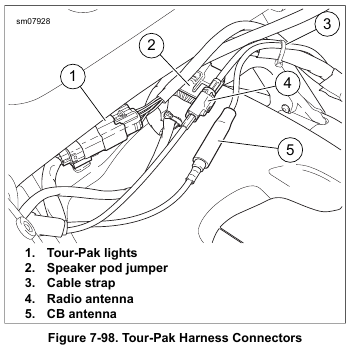
2. See Figure 7-98. Separate rear audio connector from main harness.
NOTE
If both speaker enclosures are removed, connector disassembly is not required.
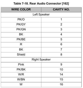
3. Remove appropriate terminals from housing. Refer to Table 7-18.
NOTE
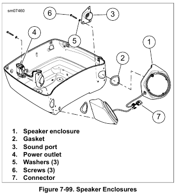
See Figure 7-99. Screws securing right speaker enclosure also secure power outlet (4).
4. Remove three screws (6) with flat washers (5) to free speaker enclosure from Tour-Pak.
5. Remove gasket (2) and sound port (3).
Installation
1. See Figure 7-99. Install sound port and new gasket (2).
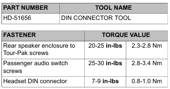
2. Install three screws with flat washers to secure speaker enclosure, sound port and power outlet (right side only) to Tour-Pak. Tighten to 20-25 in-lbs (2.3-2.8 Nm).
3. Install terminals in connector housing. Refer to Table 7-18 for cavity assignments.
4. Mate rear audio connector to main harness.
5. Install Tour-Pak liner. See 2.34 TOUR-PAK SERVICE, Tour-Pak Liner.
Disassembly
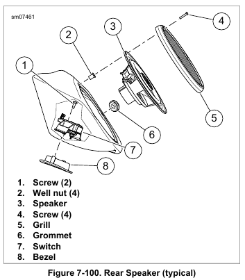
1. See Figure 7-100. Remove four screws (4).
2. Remove speaker and grille from enclosure. Disconnect terminals.
3. Right speaker:
a. Remove well nut (2) to access switch screw.
b. Remove screws securing switch assembly.
c. Remove harness and switch assembly.
d. Remove switch bezel.
NOTE
It is not necessary to remove the enclosure to service the rear speaker components.
4. Left speaker:
a. Using DIN CONNECTOR TOOL (Part No. HD-51656), remove nut and weather cap from passenger headset connector.
b. Remove passenger headset connector and harness assembly.
5. See Figure 7-99. To separate left and right harnesses, remove terminals from connector (7).
6. Remove harness grommet.
Assembly
1. Install harness grommet. The left enclosure grommet has the larger hole.
2. See Figure 7-99. If separated, assemble left and right harnesses to connector (7). Refer to Table 7-18 for cavity assignments.
3. Right speaker:
a. Install switch bezel.
b. Install harness and switch assembly with wires nearest to wall of speaker enclosure.
c. Install screws securing switch assembly. Tighten to 25-30 in-lbs (2.8-3.4 Nm).
d. Install well nut removed to access screw.
e. Route harness through grommet.
4. Left speaker:
a. Install passenger headset connector and harness assembly.
b. Install weather cap and nut to secure passenger headset connector. Using DIN CONNECTOR TOOL (Part No. HD-51656), tighten to 7-9 in-lbs (0.8-1.0 Nm).
c. Route harness under boss and through grommet.
5. See Figure 7-100. Install cable strap on harness next to inside of grommet (6) to act as strain relief.
6. Connect terminals to speaker.
NOTE
Over-tightening screws (4) can cause well nuts to pull through mounting holes.
7. Secure speaker and grille with four screws (4). Tighten carefully.
Leave a Reply