Author: Sam

  • 2015 Touring – BODY CONTROL MODULE (BCM) – INSTALLATION

    1. See Figure 7-3. Install BCM connector and rotate lock to secure.

    2. Connect BCM power wire.

    3. Install BCM in left caddy. Install main fuse.

    4. Install side cover.

    5. If installing a new BCM, it must be set up using DIGITAL TECHNICIAN II (Part No. HD-48650):
    a. Choose the VEHICLE SETUP icon.
    b. Follow the on-screen prompts.


  • 2015 Touring – BODY CONTROL MODULE (BCM) – REMOVAL

    1. Remove left side cover.

    2. Siren equipped models: With security fob present, turn ignition switch ON.

    3. Remove main fuse.

    4. Lift retaining tab and pull BCM from left caddy.

    5. See Figure 7-3. Remove BCM power wire connector (4).

    6. Push lock latch and rotate lock (2) until a click is heard. Remove BCM connector (1).


  • 2015 Touring – ELECTRONIC CONTROL MODULE (ECM) – ECM

    Removal

    1. Remove seat. See 2.30 SEAT.

    2. Free ECM from top caddy.

    3. Disconnect three ECM connectors. See A.22 TYCO GET 64 SEALED CONNECTOR.

    Installation

    1. Connect ECM connectors.

    NOTE

    Connectors are keyed to install only in the correct location.
    The color of each connector is also imprinted on the ECM adjacent to each connector.

    2. Secure ECM in top caddy.

    After installing seat, pull upward on seat to be sure it is locked in position. While riding, a loose seat can shift causing loss of control, which could result in death or serious injury. (00070b)

    3. Install seat. See 2.30 SEAT.

    4. If installing a new ECM, it must be set up using DIGITAL TECHNICIAN II (Part No. HD-48650):
    a. Choose the REFLASH icon.
    b. Follow the on-screen prompts.

    NOTES

    • Whenever a new TGS or ECM is installed, idle speed must be reset. The ECM uses the first four ignition cycles to establish the optimum idle speed. Failure to perform these steps can result in initial performance problems.

    • After installing ECM, the password learn procedure must be performed.

    5. If a new ECM was installed, reset idle speed.
    a. Place the engine run/stop switch in the RUN position.
    b. Turn the ignition switch to IGNITION and then OFF four times without starting engine. Allow at least three seconds to elapse between ignition cycles.


  • 2015 Touring – SYSTEM FUSES AND RELAYS – FUSE BLOCKS

    Main Fuse Holder

    See 7.6 ELECTRICAL CADDIES for removal and installation of the main fuse holder. See A.9 DELPHI 800 METRI-PACK SEALED MAIN FUSE HOUSING for terminal removal and installation.

    System Fuse Block

    See 7.6 ELECTRICAL CADDIES for removal and installation of the system fuse block. See A.6 DELPHI 280 METRI-PACK UNSEALED CONNECTORS for terminal removal and installation.

  • 2015 Touring – SYSTEM FUSES AND RELAYS

    NOTE

    All Touring model motorcycles use a common fuse block. Actual fuse assignment may vary based on model and options.

    Removal

    1. Remove left saddlebag. See 2.31 SADDLEBAGS.

    2. Remove left side cover.

    3. Press in tabs on the left and right sides of fuse block cover.
    Remove the cover.

    4. See Figure 7-1. Remove system fuse or relay from fuse block. Replace fuse if the element is burned. Automotive type ATO fuses are used.

    Installation

    1. See Figure 7-1. Install system fuse or relay in fuse block.

    2. Install fuse block cover.

    3. Install left side cover.

    4. Install left saddlebag. See 2.31 SADDLEBAGS.


  • 2015 Touring – SYSTEM FUSES AND RELAYS – MAIN FUSE

    Removal

    1. Remove left side saddlebag. See 2.31 SADDLEBAGS.

    2. Remove left side cover.

    3. Siren equipped models: With security fob present, turn ignition switch ON.

    4. See Figure 7-1. Pull main fuse from main fuse holder.

    Installation

    1. See Figure 7-1. Insert main fuse into main fuse holder.

    2. Install left side cover.

    3. Install left side saddlebag. See 2.31 SADDLEBAGS.


  • 2015 Touring – FASTENER TORQUE VALUES – FASTENER TORQUE VALUES IN THIS CHAPTER

    The table below lists torque values for all fasteners presented in this chapter.


  • 2015 Touring – TRANSMISSION CASE – ASSEMBLY

    Countershaft Needle Bearing Replacement

    1. Find a suitable bearing driver 1.25 in (31.75 mm) in diameter.

    2. Check bearing position.
    a. From the outside of the transmission case place the needle bearing open end first next to the bearing bore.
    b. Hold the driver squarely against the closed end of the bearing and tap the bearing into place.
    c. The bearing is properly positioned when it is driven inward flush with the outside surface of the case or to a maximum depth of 0.030 in (0.76 mm).

    3. Lubricate the bearing with SCREAMIN’ EAGLE ASSEMBLY LUBE.

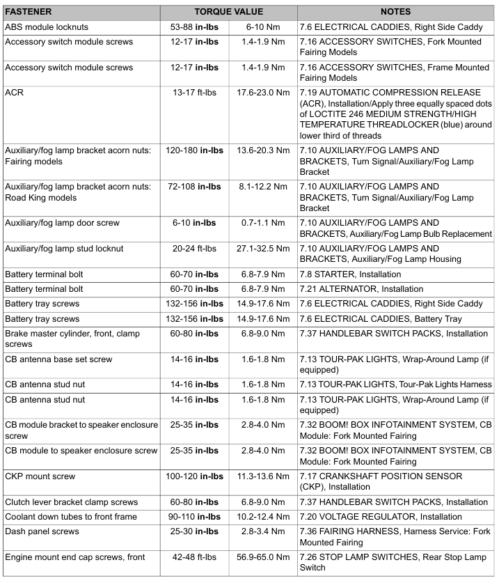
    Shifter Pawl Lever Assembly

    1. See Figure 6-59. Verify that sleeve (2) is inside transmission case.

    2. Install screw (11) and washer (10) into side of transmission case. Tighten to 18-23 ft-lbs (24.4-31.2 Nm).

    3. See Figure 6-60. Slide shifter lever centering spring (3) over shaft of shifter pawl lever assembly (2). Align opening on spring with tab on lever.

    4. Place shifter shaft lever spring (4) on shifter pawl lever assembly.

    NOTE

    Do not bend shifter shaft lever spring more than necessary for assembly.

    5. See Figure 6-61. Insert the assembly into the transmission case.

    6. See Figure 6-62. Verify that pin sits inside shifter shaft lever spring.

    7. See Figure 6-63. Using SHIFTER SHAFT SEAL INSTALLATION TOOL (Part No. HD-51337), install a new seal. Make sure the seal’s garter spring faces the transmission. Drive the seal in until the tool bottoms out on the transmission case. This installs the seal to the correct depth.

    8. See Figure 6-61. Install washer (1) and a new retaining ring (2).

    NOTE

    In next step, shifter rod lever must be installed so angle of lever is toward front of vehicle, one spline from vertical.

    9. See Figure 6-59. Install shifter rod lever (9) on the shifter pawl lever assembly shaft end using screw (8). Tighten to 18-22 ft-lbs (24.4-29.8 Nm).


  • 2015 Touring – TRANSMISSION CASE – CLEANING AND INSPECTION

    Compressed air can pierce the skin and flying debris from compressed air could cause serious eye injury. Wear safety glasses when working with compressed air. Never use your hand to check for air leaks or to determine air flow rates. (00061a)

    1. Clean all parts in solvent except the case and main drive gear needle bearings. Dry parts with low pressure compressed air.

    NOTE

    Never wash the transmission case and needle bearings with solvent. Normal cleaning methods will wash dirt or other contaminants into the bearing case (behind the needles) leading to bearing failure.

    2. See Figure 6-59. Inspect the shifter pawl lever assembly (1) for wear. Replace assembly if pawl ends are damaged. Replace centering spring (3) if elongated.

    3. Inspect the shifter spring (4). Replace if the spring fails to hold the pawl on the cam pins.

    4. Thoroughly clean the oil pan with solvent.

    5. Inspect preformed transmission top cover vent hose for damage. Replace as necessary. Use low-pressure compressed air to verify that hose and fitting are unobstructed.