Author: Sam

  • 2015 Touring – TRANSMISSION CASE – DISASSEMBLY

    Shifter Arm Assembly

    1. See Figure 6-59. After removing bearing housing assembly, remove screw (8) and shifter rod lever (9) from the shifter pawl lever assembly (1).

    2. Remove retaining ring (7), washer (6) and seal (5). Discard retaining ring and seal. Pull shifter pawl lever assembly out of the transmission case.

    3. Inspect sleeve (2) inside transmission case.

  • 2015 Touring – TRANSMISSION CASE – INSTALLATION

    1. Install new ground post at top of transmission case.
    Tighten ground post until snug.

    NOTE

    A new transmission case comes with the shifter shaft sleeve and seal, centering screw, countershaft needle bearing and main drive gear bearing and seal installed.

    2. Thoroughly wipe all engine oil from pockets in crankcase flange.

    3. Install new engine-to-transmission gasket engaging two index pins in holes of transmission flange.

    4. Verify that transmission dowels are seated. Place transmission case into position behind crankcase. Mate engine and transmission flanges.

    5. Install and tighten fasteners.
    a. Install shorter fasteners at the top, longer fasteners at the bottom. Hand tighten fasteners in a crosswise pattern.
    b. See Figure 6-58. Tighten bolts in the sequence shown to 15 ft-lbs (20.3 Nm) in the same crosswise pattern.
    c. Final tighten bolts to 34-39 ft-lbs (46.1-52.9 Nm).

    6. Install oil pan. See 3.31 OIL PAN.

    7. Install rear fork. See 2.22 REAR FORK, Installation.

    8. Install shift arm on shift shaft. Align marks made during disassembly.

    9. Install transmission and bearing housing assembly. See 6.8 TRANSMISSION ASSEMBLY, Installation.

    10. Secure battery ground cable to ground post at top of transmission case. Tighten to 66-114 in-lbs (7.5-12.9 Nm).

    11. Adjust drive belt tension. See 1.14 DRIVE BELT AND SPROCKETS.

    12. Install primary chaincase. See 5.5 PRIMARY CHAINCASE HOUSING.

    13. Install drive components. See 5.4 DRIVE COMPONENTS.

    NOTE

    Always install a new gasket between primary chaincase cover and chaincase. Failure to replace this gasket may cause primary chaincase leaks.

    14. Install primary chaincase cover. See 5.3 PRIMARY CHAINCASE COVER.

    15. Install neutral switch. Tighten to 120-180 in-lbs (13.6-20.3 Nm).

    16. Install VSS with screw. Tighten to 100-120 in-lbs (11.3-13.6 Nm).

    17. Mate VSS, O2 sensors, starter solenoid and neutral switch connectors to main harness.

    18. Install starter. See 7.8 STARTER, Installation.

    19. Install exhaust system. See 4.18 EXHAUST SYSTEM.

    20. Install drain plug. Tighten to 14-21 ft-lbs (19.0-28.5 Nm).
    Fill transmission. See 1.11 TRANSMISSION LUBRICANT.

    Do not overfill the primary chaincase with lubricant. Overfilling can cause rough clutch engagement, incomplete disengagement, clutch drag and/or difficulty in finding neutral at engine idle. (00199b)

    21.Fill primary chaincase. See 1.10 PRIMARY CHAINCASE LUBRICANT, Changing Primary Chaincase Lubricant.

    22. Fill engine oil. See 1.6 ENGINE OIL AND FILTER, Changing Oil and Oil Filter.

    Connect positive (+) battery cable first. If positive (+) cable should contact ground with negative (-) cable connected, the resulting sparks can cause a battery explosion, which could result in death or serious injury. (00068a)

    23. Connect battery cables.


  • 2015 Touring – TRANSMISSION CASE – REMOVAL

    Disconnect negative (-) battery cable first. If positive (+) cable should contact ground with negative (-) cable connected, the resulting sparks can cause a battery explosion, which could result in death or serious injury. (00049a)

    1. Disconnect battery.

    2. Drain engine oil. See 1.6 ENGINE OIL AND FILTER.

    3. Drain transmission. See 1.11 TRANSMISSION LUBRICANT.

    4. Remove starter. See 7.8 STARTER.

    5. Remove transmission assembly. See 6.8 TRANSMISSION ASSEMBLY.

    6. Remove oil pan. See 3.31 OIL PAN, Removal.

    When lifting a motorcycle using a jack, be sure jack contacts both lower frame tubes where down tubes and lower frame tubes converge. Never lift by jacking on crossmembers, oil pan, mounting brackets, components or housings. Failure to comply can cause serious damage resulting in the need to perform major repair work. (00586d)

    7. Position jack across lower frame to support rear of motorcycle. Slide wooden blocks beneath the crankcase to support the weight of the engine and transmission assembly.

    8. Remove rear fork. See 2.22 REAR FORK.

    9. Disconnect vehicle speed sensor (VSS).
    See 7.22 VEHICLE SPEED SENSOR (VSS).

    10. Disconnect neutral switch. See 7.24 NEUTRAL SWITCH, Removal.

    11. Remove battery negative ring terminal from ground post at top of transmission case.

    12. Move aside the harness that terminates at the O2 sensor, starter solenoid, neutral switch and VSS.

    13. Mark splines on shift arm and shift shaft to help with assembly. Remove shift arm from shift shaft.

    14.In a crosswise pattern, remove four fasteners that connect transmission to engine.

    NOTE

    See Figure 6-57. Do not use a hammer to remove transmission. If the transmission sticks or binds on the ring dowels, gently pry away from crankcase using the pry point.

    15. Move transmission rearward until two ring dowels in lower flange are free of crankcase. Remove transmission case from left side of the motorcycle.


  • 2015 Touring – MAIN DRIVE GEAR AND BEARING – INSTALLATION

    Improper tightening of sprocket nut can cause drive component damage. (00541b)

    Installing Main Drive Gear Bearing

    NOTE

    CROSS PLATE (Part No. HD-35316-3A) will retrofit to earlier transmissions. Note that one end of cross plate is stamped, “UP 6 SPEED”. Mount cross plate with this end pointing up for 6 speed transmissions.

    1. See Figure 6-49. Secure CROSS PLATE (Part No. HD-35316-3A) (2) on right side of transmission case with two screws (3). Position cross plate with large bolt hole aligned with center of main drive gear bearing bore.

    2. Apply a light coat of graphite lubricant to the threads of 12 IN. BOLT (Part No. HD-35316-5) (1) and install through cross plate and main drive gear bearing bore.

    3. Place main drive gear bearing (4), BEARING DRIVER (Part No. HD-35316-8) (5), BEARING (6), FLAT WASHER (7) and NUT (8) over end of bolt.

    4. Tighten nut until main drive gear bearing bottoms against lip cast into transmission case bearing bore.

    Installing Main Drive Gear

    NOTE

    See Figure 6-50. Make sure new O-ring (4) is installed onto
    main drive gear (3). Lubricate O-ring with clean engine oil.

    1. See Figure 6-50. Apply a light coat of graphite lubricant to the threads of 8 IN. BOLT (Part No. HD-35316-4A) (1) and insert through WASHER (Part No. HD-35316-7) (2) and main drive gear (3). Insert assembly into transmission case, through main drive gear bearing.

    2. Place INSTALLER CUP (Part No. HD-35316-12) (5), BEARING (6), FLAT WASHER (7) and NUT (8) over end of bolt.

    3. Tighten nut until main drive gear contacts main drive gear bearing.

    NOTE

    See Figure 6-51. Retaining ring must be installed with the flat side facing the bearing and the opening within the ninety degree range shown.

    4. See Figure 6-52. Install new retaining ring (2).

    Installing Main Drive Gear Large Seal

    1. See Figure 6-52. Install PILOT (Part No. HD-47856-2) over end of main drive gear bearing inner race.

    2. Coat lips of new main drive gear seal with transmission lubricant.

    3. See Figure 6-53. Place seal over pilot with garter spring facing bearing, and position seal squarely in end of crankcase bore.

    NOTE

    ADAPTER (Part No. HD-47856-3) and main drive gear have right-hand threads.

    4. See Figure 6-54. Install ADAPTER (Part No. HD-47856-3) onto end of main drive gear until it contacts main drive gear.

    5. See Figure 6-55. Slide INSTALLER (Part No. HD-47856-1) (1) over adapter until cupped end of installer is flat against seal.

    6. Install NUT (Part No. HD-47856-6) (2) onto end of adapter against installer.

    7. See Figure 6-56. Hold adapter from rotating and tighten large nut with CROW’S FOOT WRENCH (Part No. HD-47856-7) (1) attached to a 1/2 in breaker bar (2) until outer face of seal is flush with outer edge of transmission bore.

    NOTE

    Seal depth will be controlled by tool. Seal can be recessed as much as 0.030 in. (0.762 mm) below outer edge of bore.

    8. Remove nut, installer, adapter and pilot.

    9. Install bearing housing and transmission components. See 6.8 TRANSMISSION ASSEMBLY, Installation.

    10. Install sprocket and drive belt. See 5.9 TRANSMISSION SPROCKET. Do not adjust belt at this time.

    11. Install the bearing inner race on the transmission mainshaft. See 6.8 TRANSMISSION ASSEMBLY, Assembly.

    12. Install the primary chaincase housing. See 5.5 PRIMARY CHAINCASE HOUSING, Installation.

    13. Install the clutch assembly, primary chain, chain tensioner assembly and compensating sprocket components. See 5.4 DRIVE COMPONENTS, Installation.

    14. Install the primary chaincase cover. See 5.3 PRIMARY CHAINCASE COVER, Installation.

    15. Adjust the drive belt. See 1.14 DRIVE BELT AND SPROCKETS, Setting Belt Deflection.

    16. Install exhaust system. See 4.18 EXHAUST SYSTEM.


  • 2015 Touring – MAIN DRIVE GEAR AND BEARING – MAINSHAFT SEAL REPLACEMENT

    See Figure 6-46. To replace the mainshaft seal with the main drive gear installed, use the MAIN DRIVE GEAR SEAL INSTALLER (Part No. HD-47933).

    1. Remove the damaged seal using a seal remover or rolling head pry bar.

    2. Inspect bore to be sure it is clean and smooth.

    3. See Figure 6-47. Place the seal protector sleeve (1) over the end of the mainshaft. Lightly lubricate the protector sleeve and seal ID with clean transmission oil.

    4. Verify that the garter spring is in place on the lip of the new oil seal. Apply a light coat of clean oil to the seal lip.

    5. Squarely seat the mainshaft seal (2) on the seal protector sleeve with the garter spring facing the bearing.

    6. See Figure 6-48. Using MAIN DRIVE GEAR SEAL INSTALLER (Part No. HD-47933), hand press seal onto place until seal driver contacts end of main drive gear. A rubber mallet may be used to lightly tap driver, if necessary.


  • 2015 Touring – MAIN DRIVE GEAR AND BEARING – CLEANING AND INSPECTION

    1. Clean all parts in solvent except the transmission case and needle bearings. Dry with compressed air.

    NOTE

    Never wash the transmission case and needle bearings with solvent unless replacing the needle bearings. Normal cleaning methods will wash dirt or other contaminants into the bearing case (behind the needles) and will lead to bearing failure.

    2. Inspect the main drive gear for pitting and wear. Replace if necessary.

    3. Inspect the needle bearings inside the main drive gear.
    Replace the needle bearings if the mainshaft race is pitted or grooved.

    4. Replace the sprocket if teeth are cracked or worn. See 5.9 TRANSMISSION SPROCKET, Cleaning and Inspection for more information.

    5. Inspect the needle bearings on the inside of the main drive gear. If mainshaft race surface appears pitted or grooved, replace these bearings.

    NOTE

    If replacing the main drive gear needle bearings and/or seal, continue as follows. Otherwise, proceed to 6.10 TRANSMISSION CASE, Assembly.

    Needle Bearing Replacement

    NOTES

    • See Figure 6-42. When replacing needle bearings, discard original retaining rings (1) and install replacement retaining rings (2).
    • To install the inner main drive gear needle bearings and mainshaft seal, use MAIN DRIVE GEAR BEARING AND SEAL INSTALLATION TOOL (Part No. HD-47932).

    1. See Figure 6-41. Remove mainshaft seal (6). Remove retaining rings (1), needle bearings (2) and spacer (5) from main drive gear (3). Discard retaining rings.

    2. Remove and discard O-ring (4).

    3. See Figure 6-43. Install clutch side needle bearing using an arbor press and the 0.400 in. step end of tool as shown. Press until tool contacts gear.

    NOTE

    An alternative method is provided which allows the mainshaft seal to be pressed into place after installation of the main drive gear. See 6.9 MAIN DRIVE GEAR AND BEARING, Mainshaft Seal Replacement.

    4. See Figure 6-44. Turn over tool and press in mainshaft seal using the 0.090 in. step with garter spring side down.

    5. Install spacer.

    6. See Figure 6-45. Turn over the main drive gear in the arbor press. With the tool at the 0.188 in. step, press inner bearing until tool contacts gear.

    7. See Figure 6-41. Install new retaining rings (1).

    8. Install new O-ring (4) into groove in main drive gear.


  • 2015 Touring – MAIN DRIVE GEAR AND BEARING – REMOVAL

    NOTE

    Leave transmission case in the frame unless the case it self must be replaced. For illustration purposes, some photographs may show the case removed.

    1. Remove exhaust system. See 4.18 EXHAUST SYSTEM.

    2. Remove primary chaincase cover, clutch assembly, primary chain, compensating sprocket, and primary chaincase and remove bearing inner race from the transmission mainshaft. See 5.5 PRIMARY CHAINCASE HOUSING.

    3. Remove transmission bearing housing. See 6.8 TRANSMISSION ASSEMBLY.

    NOTE

    Main drive gear and bearing can be removed with the transmission case in the frame after removing bearing housing. Use MAIN DRIVE GEAR/BEARING REMOVER AND INSTALLER (Part No. HD-35316-C).

    4. Remove retaining ring.

    NOTES

    • The main drive gear bearing and retaining ring must be replaced if the main drive gear is removed. The bearing will be damaged during the removal procedure.
    • The CROSS PLATE (Part No. HD-35316-3A) is stamped, “UP 6 SPEED”. Mount cross plate with this end pointing up.

    5. See Figure 6-38. Place CROSS PLATE (Part No. HD-35316-3A) (1) on right side of transmission case as shown, and secure with two screws (2). Position cross plate so that large bolt hole in cross plate is lined up with center of main drive gear (4).

    6. Apply a light coat of graphite lubricant to the threads of the 12 IN. BOLT (Part No. HD-35316-5) (3) and insert through cross plate and main drive gear.

    7. At left side of transmission case, place WASHER (Part No. HD-35316-7), BEARING (Part No. RS-25100-200) (6), flat washer (7) and nut (8) over end of bolt. Tighten nut until main drive gear is free.

    NOTES

    • When removing the main drive gear, the gear is pressed out against the resistance of the bearing inner race.
    Without any support at the inner race, the bearing is destroyed. Whenever the main drive gear is removed the main drive gear bearing must also be replaced.
    • See Figure 6-39. When the main drive gear is removed, a portion of the bearing inner race remains attached to the main drive gear. If the main drive gear is to be reused, this inner race must be removed first.

    8. Remove tool and remove gear from gearcase.

    9. See Figure 6-39. Use WEDGE ATTACHMENT (Part No. HD-95637-46B) and LONG BOLTS (Part No. HD-95637-10) to remove inner race from main drive gear.

    10. Remove large main drive gear oil seal.

    11. Remove retaining ring from bearing bore.

    12. See Figure 6-40. Slide PILOT (Part No. HD-35316-10) (3) over small end of BEARING DRIVER (Part No. HD-35316-9) (2).

    13. Apply a light coat of graphite lubricant to the threads of the 8 IN. BOLT (Part No. HD-35316-4A) (1) and insert through bearing driver and pilot.

    14. Insert bolt with bearing driver and pilot into right side of transmission case, through main drive gear bearing (4). Make sure bearing driver fits up against main drive gear bearing and pilot is centered in bearing bore.

    15. At left side of case, slide RECEIVER CUP (Part No. HD-35316-11) (5) onto bolt and over main drive gear bearing.
    Install BEARING (Part No. RS-25100-200) (6), flat washer (7) and nut (8) over end of bolt.

    NOTE

    Support bearing remover assembly as you remove bearing in the following step. Entire assembly will fall out of transmission case when bearing comes free.

    16. Tighten nut until main drive gear bearing is free.

    17. Discard main drive gear bearing.


  • 2015 Touring – TRANSMISSION ASSEMBLY – INSTALLATION

    1. Cover mainshaft clutch hub splines with tape to prevent the splines damaging the main drive gear oil seal.

    2. Verify that two ring dowels are in place on bearing housing flange. Place a new gasket on the ring dowels.

    3. Apply clean transmission lubricant to the main drive gear bearings.

    NOTE

    Contact with the dipstick will prevent installation of transmission assembly.

    4. Remove the transmission dipstick before installing transmission assembly.

    5. Install the transmission assembly in the transmission case with a new gasket.

    6. See Figure 6-35. Install exhaust bracket using long screws (1). Install remaining bearing housing screws (2).

    7. See Figure 6-36. Tighten bearing housing screws in the sequence shown to 22-25 ft-lbs (29.8-33.9 Nm).

    8. Install mainshaft bearing inner race. See 5.9 TRANSMISSION SPROCKET.

    9. See Figure 6-37. Install pushrod assembly (items 2-5) in mainshaft hole. Secure with new retaining ring (1) if removed.

    10. Install the clutch release cover, using a new gasket. See 6.5 CLUTCH RELEASE COVER: CABLE CLUTCH.

    11. Rotate shifter cam pawl forward and lower into place on shift cam. Install new transmission top cover gasket. Install transmission top cover. Tighten fasteners to 90-120 in-lbs (10.2-13.6 Nm).

    12. Install vent hose to top cover fitting, if removed.

    13. Install transmission sprocket nut. See 5.9 TRANSMISSION SPROCKET.

    14. Install primary chaincase, clutch assembly and primary cover. See 5.3 PRIMARY CHAINCASE COVER, Installation.

    15. Clean transmission drain plug. Install drain plug with new O-ring. Tighten to 14-21 ft-lbs (19.0-28.5 Nm).

    16. Fill transmission to proper level with fresh transmission fluid. See 1.11 TRANSMISSION LUBRICANT.

    17. Adjust drive belt tension. See 1.14 DRIVE BELT AND SPROCKETS.

    18. Install exhaust system. See 4.18 EXHAUST SYSTEM.


  • 2015 Touring – TRANSMISSION ASSEMBLY – ASSEMBLY

    Installing Bearing Housing Bearings

    NOTES

    • Always replace bearing housing bearing if the shaft was pressed out.
    • Always use a plate to support the bearing housing when pressing in bearings.
    • When pressing new bearings into bearing housing, press on the outside diameter of the bearing side with the numbers stamped on it.

    1. Support the bearing housing from the opposite side at the bearing bores with a flat plate.

    2. Position new bearing over bore with number side UP.

    3. Press the outer diameter of the bearing until the bearing seats in the bore.

    4. See Figure 6-26. Install beveled retaining ring (1) with the flat side against the bearing.

    Countershaft

    NOTES

    • Replace retaining ring and all gear roller bearings with new parts during assembly. Lubricate needle bearings and races with SCREAMIN’ EAGLE ASSEMBLY LUBE before installation.
    • Install securing segments so the side with the rounded edge is facing up and the side with the straight edge is down. Verify segments fully engage grooves in countershaft.
    • One side of the 2nd, 3rd and 4th gear lock rings have a waved, stepped face. The waved, stepped face always faces the securing segments.

    1. See Figure 6-25. Install new needle bearing, countershaft 4th gear (4), guiding hub (2), dog ring (3) securing segments and 4th gear lock ring (1) on countershaft.

    2. See Figure 6-24. Install new needle bearing, countershaft 3rd gear (3), internal spline washer (2) and securing segments (1).

    3. See Figure 6-23. Place countershaft 3rd gear lock ring over securing segments.

    NOTES

    • In next step, the side of the guiding hub with the deeper counterbore faces countershaft 2nd gear.
    • Countershaft 2nd gear bearing is wider than other bearings on the countershaft.

    4. See Figure 6-22. Install new needle bearing, countershaft 2nd gear (4), guiding hub (2), dog ring (3) and securing segments (1) on countershaft.

    5. See Figure 6-21. Place lock ring over securing segments with the stepped face of the lock ring against the securing segments.

    6. See Figure 6-20. Install new needle bearing, countershaft 1st gear (2) and washer (1).

    NOTES

    • If installing countershaft only, hold countershaft 3rd and 4th gear shift dog up while pressing bearing housing bearing on to countershaft.
    • Failure to press on inner bearing races while pressing bearings on the shafts will damage the bearings.

    7. See Figure 6-28. Place countershaft in an arbor press supporting countershaft 6th gear. Using a suitable sleeve, press on inner bearing race until bearing housing bearing contacts countershaft 1st gear washer.

    Mainshaft

    NOTES

    • Failure to press on inner bearing race while pressing bearing on the shaft will damage the bearing.
    • See Figure 6-29. Hold dog ring so that it is engaged with countershaft 3rd gear during the press procedure. Otherwise bearing and gear damage is possible.

    1. Place mainshaft in an arbor press, supporting mainshaft 4th gear.

    2. Place rear bearing housing bearing over mainshaft. Using a suitable sleeve, press on inner bearing race until bearing housing bearing contacts mainshaft 1st gear.

    3. See Figure 6-18. With bearing housing on end (shafts pointing upward), install new bearing and mainshaft 5th gear (4).

    4. Verify guiding hub counterbore is facing mainshaft 5th gear. Install guiding hub (2) and dog ring (3).

    5. Install new retaining ring using TRANSMISSION SHAFT RETAINING RING PLIERS (Part No. J-5586A) (1).

    Shifter Cam/Shifter Forks

    1. Using dog rings, lock two gears in place. Temporarily place transmission assembly into transmission case.

    2. Install new nuts on mainshaft and countershaft. Tighten to 85-95 ft-lbs (115.3-128.8 Nm).

    3. Remove transmission assembly from case.

    4. Place bearing housing on bench with shafts pointing upward.

    5. If removed, install detent arm assembly:
    a. See Figure 6-30. Clean detent screw mounting hole in transmission bearing housing.
    b. Assemble new detent screw, detent arm, sleeve and detent spring. Make certain to orient spring and detent arm as shown.
    c. Mount detent assembly in bearing housing as shown.
    d. Tighten to 120-150 in-lbs (13.6-17.0 Nm).

    6. See Figure 6-31. Using screwdriver (1), pull detent arm back to allow installation of shift cam assembly.

    7. Install shift cam assembly (5).

    8. See Figure 6-32. Install lock plate (2) and new lock plate fasteners (3). Tighten to 57-63 in-lbs (6.4-7.1 Nm).

    NOTE

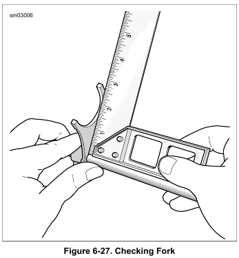
    See Figure 6-33. The forks are different from each other and are identified as shown.

    9. See Figure 6-34. Insert shifter fork (2) into the slot of the dog ring in between mainshaft 5th and 6th gear.

    10. Slide long shift shaft through 5th and 6th gear shifter fork.
    Install shaft in hole in bearing housing.

    11. Install short shift shaft:
    a. Insert shifter fork (6) into the slot of the dog ring in between countershaft 3rd and 4th gear.
    b. Insert shifter fork (9) into the slot of the dog ring in between countershaft 1st and 2nd gear.
    c. Slide short shift shaft through countershaft shifter forks.
    d. Install shaft in hole in bearing housing.

    NOTE

    If main drive gear was removed, install it now. See 6.9 MAIN DRIVE GEAR AND BEARING.


  • 2015 Touring – TRANSMISSION ASSEMBLY – CLEANING AND INSPECTION

    1. Clean all parts with solvent. Dry parts with low pressure compressed air.

    2. Check gear teeth for damage. Replace gears that are pitted, scored, rounded, cracked or chipped.

    3. Inspect the engaging dogs and pockets on the dog rings. Replace the dog rings if dogs and/or pockets are rounded, battered or chipped.

    4. Inspect guiding hubs. Replace guiding hubs if splines are rounded, battered or chipped.

    5. Inspect shift fork shafts. Replace if bent or damaged.

    6. Inspect shift forks for wear or signs of overheating. Replace a shift fork if it is excessively worn or shows signs of overheating.

    7. See Figure 6-27. Using a small square, verify the shift forks are square. If shift fork does not rest directly on the square, then it is bent and must be replaced.

    8. Inspect shift drum and bearing. Replace shift drum assembly if drum or bearing are damaged.

    9. Clean shift cam lock plate mounting holes in transmission bearing housing.

    10. Inspect bearing housing bearings. Bearings must rotate freely without drag. Replace the bearings if pitted, grooved or if the shafts were removed.