Author: Sam

  • 2015 Touring – SHIFTER LINKAGE – SHIFTER ROD ADJUSTMENT

    The shifter rod length is set at the factory and should not require adjustment under normal circumstances. However, if full engagement or full lever travel is not achieved, adjust the shifter rod.

    NOTE

    Do not allow shift levers to contact footboard when shifting.
    This prevents proper gear engagement. Contact may also damage the transmission.

    1. See Figure 6-2. Remove nut (10), lockwasher (9) and flat washer (7) to free front end of shifter rod from inner shift arm.

    2. Loosen jamnuts (1) and adjust rod (2) as necessary.

    3. Install flat washer, lockwasher and nut to fasten shifter rod to inner shift arm.

    4. Tighten locknut (10) to 70-90 in-lbs (7.9-10.2 Nm).

    5. Tighten jamnuts (1) to 80-120 in-lbs (9.0-13.6 Nm).


  • 2015 Touring – TRANSMISSION – POWER FLOW

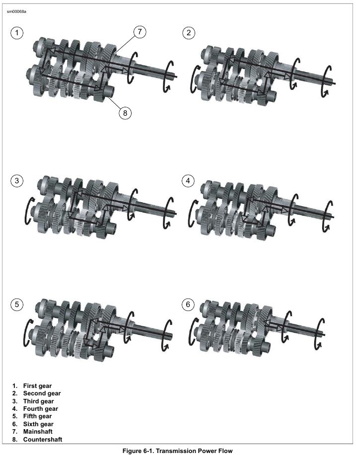
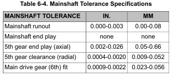
    See Figure 6-1. The 6-speed transmission consists of two parallel shafts supporting six gears each. The longer, or mainshaft (7), also supports the clutch and serves as the input shaft. The shorter shaft is called the countershaft (8).

    Each gear on the mainshaft is in constant mesh with a corresponding gear on the countershaft. Each of these six pairs of gears makes up a different speed in the transmission.

    The transmission gears are divided into two types, gears that rotate with the shaft, and gears that spin freely on the shaft. A gear that rotates with the shaft always meshes with a freewheeling gear. Also, three dog rings are able to slide sideways on the shaft. These dog rings are used to change transmission speeds. The dogs on the sides of dog rings engage dogs on adjacent freewheeling gears, transmitting power through the transmission.

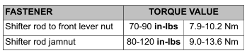
    Gear shifting is accomplished by three forks which fit into grooves machined into the dog rings that slide on the guide hubs. The position of the shifter forks is controlled by a drumshaped shifter cam located in the transmission bearing housing.

    Neutral

    Power is introduced to the transmission through the clutch. In neutral, with the clutch engaged, the mainshaft 1st, 2nd, 3rd and 4th gears are rotating. No power is transferred to the countershaft since countershaft 1st, 2nd, 3rd and 4th gears are freewheeling gears.

    First Gear

    When the transmission is shifted into first gear, the dog ring between countershaft 1st and 2nd, which rotates with the countershaft, engages countershaft 1st, which has been spinning freely on the countershaft driven by mainshaft 1st.

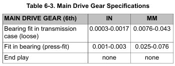
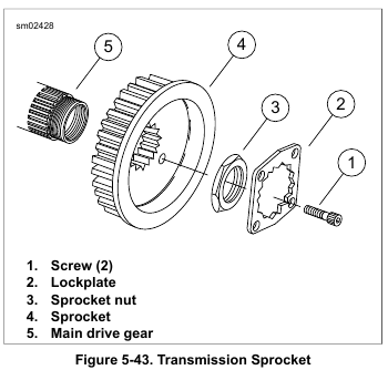
    Now countershaft 1st is no longer freewheeling, but locked to the countershaft causing the countershaft and countershaft 6th to turn. Countershaft 6th transmits the power to the main drive gear and the sprocket as shown (1).

    Second Gear

    Second gear is engaged when the dog ring between countershaft 1st and 2nd is shifted out of countershaft 1st and engages countershaft 2nd. This locks countershaft 2nd to the countershaft to complete the power flow as shown (2).

    Third Gear

    Two shifter forks are used to make the shift from second to third. One fork moves the dog ring between countershaft 1st and 2nd to its neutral position. At the same time another fork engages the dog ring between countershaft 3rd and 4th with countershaft 3rd. This locks countershaft 3rd to the countershaft to complete the power flow as shown (3).

    Fourth Gear

    Fourth gear is engaged when the dog ring between countershaft 3rd and 4th is shifted out of countershaft 3rd and engages countershaft 4th. This locks countershaft 4th to the countershaft to complete the power flow as shown (4).

    Fifth Gear

    Two shifter forks are used to make the shift from fourth to fifth. One fork moves the dog ring between countershaft 3rd and 4th to its neutral position. At the same time another fork engages the dog ring between mainshaft 5th and 6th with mainshaft 5th. This locks mainshaft 5th to the mainshaft to complete the power flow as shown (5).

    Sixth Gear

    The shift from fifth to sixth gear occurs when the dog ring between mainshaft 5th and 6th is shifted out of mainshaft 5th. It is shifted directly into the main drive gear (6th gear). The main drive gear is locked to the mainshaft. this results in a direct one-to-one drive ratio from the clutch to the sprocket as shown (6).


  • 2015 Touring – SPECIFICATIONS: TRANSMISSION – SPECIFICATIONS

    NOTE

    Final gear ratios indicate the number of mainshaft revolutions required to drive the output sprocket one revolution.

  • 2015 Touring – DRIVE BELT – INSTALLATION

    Never bend belt forward into a loop smaller than the drive sprocket diameter. Never bend belt into a reverse loop. Over bending can damage belt resulting in premature failure, which could cause loss of control and death or serious injury. (00339a)

    1. Install belt over transmission sprocket.

    2. Install the primary chaincase housing. See 5.5 PRIMARY CHAINCASE HOUSING, Installation.

    NOTE

    Always install a new gasket between primary chaincase cover and chaincase. Failure to replace this gasket may cause primary chaincase leaks.

    3. Install primary chain assembly. See 5.4 DRIVE COMPONENTS.

    4. Install primary chaincase cover. Fill primary chaincase with lubricant. See 5.3 PRIMARY CHAINCASE COVER.

    5. Install rear fork and rear wheel. See 2.22 REAR FORK.

    6. Adjust belt tension. See 1.14 DRIVE BELT AND SPROCKETS.


  • 2015 Touring – DRIVE BELT – REMOVAL AND ADJUSTMENT

    Adjustment

    See 1.14 DRIVE BELT AND SPROCKETS, Setting Belt Deflection.

    Removal

    1. Remove rear wheel and rear fork. See 2.22 REAR FORK.

    2. Remove primary chain, clutch, engine compensating sprocket and chain adjuster as an assembly. See 5.4 DRIVE COMPONENTS.

    3. Remove primary chaincase housing. See 5.5 PRIMARY CHAINCASE HOUSING, Removal.

    4. Remove belt from transmission sprocket.


  • 2015 Touring – TRANSMISSION SPROCKET – INSTALLATION

    NOTE

    Install sprocket nut only while transmission is installed in frame. Failure to do so will result in damage to transmission and/or transmission stand.

    1. Place transmission sprocket in position. Install the belt on the sprocket as the sprocket is installed.

    2. If reusing the sprocket nut, apply LOCTITE 271 HIGH STRENGTH THREADLOCKER (red) to the threads of the sprocket nut.

    NOTES

    • Never get oil on the threads of the sprocket nut or the integrity of the lock patch may be compromised.
    • The transmission sprocket nut has right-hand threads.
    Turn the nut clockwise to install.

    3. See Figure 5-43. Apply a thin film of clean engine oil on the inner face of the sprocket nut (3) and the outer face of the sprocket (4) where the two parts contact each other.
    Install the sprocket nut finger-tight.

    4. See Figure 5-45. Lock transmission sprocket with the FINAL DRIVE SPROCKET LOCKING TOOL (Part No. HD-46282A) (2). The locking tool must rest against the rear fork pivot (3).

    5. Install PILOT (Part No. HD-94660-2) on mainshaft.

    6. Using MAINSHAFT LOCKNUT WRENCH (Part No. HD-47910), tighten sprocket nut to 100 ft-lbs (135.6 Nm) initial torque.

    7. Loosen sprocket nut one full turn.

    8. Tighten to 35 ft-lbs (47.5 Nm ).

    NOTE

    See Figure 5-46. To determine proper angles during final tightening, scribe lines (3) or use TORQUE ANGLE GAUGE (Part No. SNAP-ON TA360) after the 35 ft-lbs (47.5 Nm) torque is applied.

    9. Continue an additional 35-40 degrees (35-40 degrees).

    NOTE

    The lockplate has four screw holes and can be installed either side out. If the screw holes cannot be properly aligned, tighten the nut slightly to align. Do not exceed 45 degrees. Never LOOSEN nut to align the screw holes.

    10. Install lockplate over transmission sprocket nut with two lockplate holes aligned with tapped holes in sprocket.

    NOTES

    • New screws have lock patches.
    • Screws can be reused up to three times if LOCTITE 271 HIGH STRENGTH THREADLOCKER (red) is applied before installation.
    • Always install BOTH screws.

    11. See Figure 5-43. Install two screws (1) to secure lockplate (2). Tighten to 90-120 in-lbs (10.2-13.6 Nm).

    12. Install primary chain assembly. See 5.4 DRIVE COMPONENTS.

    NOTE

    Always install a new gasket between primary cover and housing. Not replacing this gasket may cause primary chaincase leaks.

    13. Install primary chaincase cover. Fill primary chaincase.
    See 5.3 PRIMARY CHAINCASE COVER.

    14. Verify pivot shaft torque. See 2.22 REAR FORK.

    15. Adjust drive belt deflection. See 1.14 DRIVE BELT AND SPROCKETS.


  • 2015 Touring – TRANSMISSION SPROCKET – CLEANING AND INSPECTION

    1. Using a non-volatile cleaning solvent, clean sprocket of all grease and dirt.

    2. Inspect belt and sprocket. See 1.14 DRIVE BELT AND SPROCKETS, Inspection.

    3. Inspect both main drive gear and mainshaft seals. Replace if damaged.

  • 2015 Touring – TRANSMISSION SPROCKET – REMOVAL

    1. Remove primary chaincase. See 5.5 PRIMARY CHAINCASE HOUSING.

    2. Loosen drive belt tension. See 1.14 DRIVE BELT AND SPROCKETS.

    NOTE

    Remove sprocket nut only while transmission is installed in frame. Failure to do so will result in damage to transmission and/or transmission stand.

    3. See Figure 5-43. Remove two screws (1) and lockplate (2).

    4. See Figure 5-44. Install FINAL DRIVE SPROCKET LOCKING TOOL (Part No. HD-46282A) (2) so that arm of tool rests against bottom of rear fork pivot (1).

    NOTE

    Sprocket nut has a right-hand thread.

    5. Install PILOT (Part No. HD-94660-2) on mainshaft.

    6. Remove the sprocket nut (3) using MAINSHAFT LOCKNUT WRENCH (Part No. HD-47910) (1).

    7. Remove sprocket, allowing belt to slip from sprocket as sprocket is removed.


  • 2015 Touring – HYDRAULIC CLUTCH RELEASE BEARING AND PUSHROD – INSTALLATION

    1. See Figure 5-41. Pressing on the outer race, press a new release bearing (4) into bearing plate (3).

    2. Assemble release rod (5) to bearing.

    3. Install new retainer (2).

    4. Install pushrod if removed.

    5. Seat the bearing plate in the clutch. Install bearing plate retaining ring (1).

    NOTE

    Before installing the clutch inspection cover, check release plate movement.

    Measure Release Plate Movement

    1. Attach a dial indicator to measure pushrod axial movement.

    Insufficient clutch-release plate movement can lead to difficulty or inability to shift, causing loss of control, which could result in death or serious injury. (00345a)

    2. Actuate the clutch lever to measure the axial movement of the pushrod and the clutch-release plate assembly. The minimum axial movement must be as specified. Refer to Table 5-4.

    NOTE

    Proper bleeding of the system will typically yield plate movement greater than specification. If clutch release plate movement is less than specification, bleed system and measure plate movement again.

    Install Clutch Inspection Cover

    1. Thoroughly clean all gasket material from clutch inspection cover and mating surface on primary cover.

    2. See Figure 5-42. Install clutch inspection cover with new gasket. Make sure the correct side of the gasket faces the clutch inspection cover. In star pattern, tighten screws to 84-108 in-lbs (9.5-12.2 Nm).

    3. Connect negative battery cable to battery.

    After installing seat, pull upward on seat to be sure it is locked in position. While riding, a loose seat can shift causing loss of control, which could result in death or serious injury. (00070b)

    4. Install seat.