Author: Sam

  • 2015 Touring – PRIMARY CHAINCASE HOUSING – MAINSHAFT BEARING AND SEAL

    Removal

    Wear safety glasses or goggles when removing or installing retaining rings. Retaining rings can slip from the pliers and could be propelled with enough force to cause serious eye injury. (00312a)

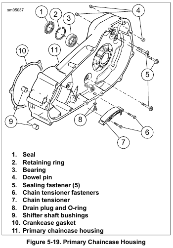
    1. See Figure 5-19. Remove seal (1). Use a seal remover or rolling head pry bar for best results.

    2. Remove retaining ring (2).

    NOTE

    Support the bearing support area on the transmission side of the primary chaincase while pressing bearing out.

    3. Place inner primary chaincase in an arbor press with clutch side up.

    4. Press out bearing from clutch side applying pressure to the outer race.

    Installation

    1. Inspect the bearing bore to verify that it is clean and smooth

    NOTE

    Support the bearing support area on the clutch side of the primary chaincase while pressing bearing in.

    2. Place primary chaincase in arbor press with the transmission side up.

    3. Apply a thin film of oil to outer diameter of bearing.

    4. Applying pressure to the outer race, press new bearing letter side up until it makes solid contact with the bearing support area.

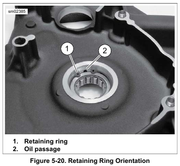
    5. See Figure 5-20. Retaining ring (1) must be oriented as shown to prevent blocking of oil passage (2). Install retaining ring. Verify that the ring is fully seated in the groove and is properly oriented.

    NOTES

    • The garter spring side of the oil seal is also identified by the words “OIL SIDE.”

    • Install oil seal with a seal driver that will press only against outer rim of oil seal, NOT against the inner area.

    • Minimum allowable depth: Oil seal case is flush with machined surface of primary housing.

    • Maximum allowable depth: Oil seal case contacts retaining ring.

    6. Install mainshaft oil seal:
    a. Lubricate the OD of the new seal with SCREAMIN’ EAGLE ASSEMBLY LUBE. Place over bore with the lip garter spring side (stamped “OIL SIDE”) facing toward the bearing.
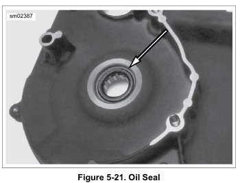
    b. See Figure 5-21. Press the seal into bore until outer edge of seal is flush with machined surface of inner primary housing.

    7. Lubricate the bearing and seal lip with multi-purpose grease or SCREAMIN’ EAGLE ASSEMBLY LUBE.


  • 2015 Touring – PRIMARY CHAINCASE HOUSING – INSPECTION

    1. Inspect primary chaincase for cracks or damaged gasket surface.

    2. Check the mainshaft bearing. Replace if bearing does not rotate freely. Replace the lip seal. See 5.5 PRIMARY CHAINCASE HOUSING, Mainshaft Bearing and Seal.

    3. Inspect shifter shaft bushings. Replace if worn or damaged. See 5.5 PRIMARY CHAINCASE HOUSING, Shifter Shaft Bushings.


  • 2015 Touring – PRIMARY CHAINCASE HOUSING – REMOVAL

    To prevent accidental vehicle start-up, which could cause death or serious injury, disconnect negative (-) battery cable before proceeding. (00048a)

    1. Disconnect negative battery cable.

    2. Remove primary chaincase cover. See 5.3 PRIMARY CHAINCASE COVER, Removal.

    3. Remove starter. See 7.8 STARTER, Removal.

    4. Remove primary chain, clutch and compensating sprocket. See 5.4 DRIVE COMPONENTS, Removal.

    5. See Figure 5-19. Remove five sealing fasteners (5) and remove primary chaincase housing (11). Discard the crankcase gasket (10) and sealing fasteners.


  • 2015 Touring – DRIVE COMPONENTS – INSTALLATION

    NOTES

    • Install the primary chain, compensating sprocket and clutch as a single unit.
    • The O-ring inside the shaft extension is for manufacturing assembly only and has no replacement part.

    1. See Figure 5-9. Apply a thin layer of primary chaincase oil to the inner diameter of the compensating sprocket (6) and the splines of shaft extension (1). Install shaft extension.

    NOTE

    Outer diameter of spring washers must contact each other.

    2. Install large spring washers (2) and medium spring washers (3).

    3. Install small spring washer (4) so outer diameter will contact sliding cam (5).

    4. Install the drive components (primary chain, compensating sprocket and clutch assembly).

    5. Lightly lubricate thrust bearing (8). Install thrust washers (7), bearing (8), retainer (9) and new bolt (10). Hand tighten.

    NOTE

    Clutch hub mainshaft nut has left-hand threads. Turn counter clockwise to install.

    6. Clean and prime threads of clutch hub mainshaft nut. Apply two drops of LOCTITE 262 HIGH STRENGTH THREAD LOCKER AND SEALANT (red) to the threads. Start nut onto mainshaft. Hand-tighten.

    7. See Figure 5-12. Place the PRIMARY DRIVE LOCKING TOOL (Part No. HD-48219) between the teeth of the engine and clutch sprockets as shown.

    NOTE

    The compensating sprocket bolt is a T70 drive. Use T70 SOCKET BIT (Part No. Snap-on STX70E), T70 SOCKET BIT (Part No. OTC 6198) or equivalent.

    8. Tighten compensating sprocket bolt (1) to 100 ft-lbs (135.6 Nm).

    9. Loosen one-half turn.

    10. Final tighten to 175 ft-lbs (237.3 Nm).

    11. See Figure 5-13. Install the PRIMARY DRIVE LOCKING TOOL (Part No. HD-48219) between the teeth of the engine and clutch sprockets as shown.

    12. Tighten clutch hub mainshaft nut (2) to 70-80 ft-lbs (94.9-108.5 Nm). Remove primary drive locking tool.

    13. See Figure 5-14. Install release plate (2) with locknut (3) and adjuster screw into clutch hub bore. The word “OUT” stamped on the release plate faces out.

    Wear safety glasses or goggles when removing or installing retaining rings. Retaining rings can slip from the pliers and could be propelled with enough force to cause serious eye injury. (00312a)

    14. Inspect retaining ring (1) and replace if necessary. Install retaining ring in clutch hub bore. Verify the retaining ring is completely seated in the groove.

    15. Adjust clutch. See 1.12 CLUTCH CABLE: ROAD KING, Adjustment.

    NOTES

    Primary chain tensioner is non-repairable. If tensioner is worn or damaged, replace assembly.

    16. Tensioner parts can be disassembled. If primary chain tensioner becomes disassembled, assemble in order shown:
    a. See Figure 5-15. Locate end of spring rod (2) on roll pin (3).
    b. See Figure 5-16. Slide wedge (2) of primary chain tensioner in direction of arrow until all travel is removed.
    c. See Figure 5-17. Push shoe (1) down until it contacts wedge. Keep tension on shoe so wedge stays in place.
    d. Insert cable strap (2) as shown to hold wedge in place.
    Verify end of cable strap is located below primary chain tensioner. Cable strap will hang below primary cover gasket surface and serve as a reminder to remove before installing primary cover.

    NOTE

    Primary chain tensioner will not complete chain adjustment until vehicle is ridden. Test ride vehicle after tensioner removal/installation to verify proper adjustment.

    17. See Figure 5-18. Install primary chain tensioner (1) with fasteners (2). Tighten to 21-24 ft-lbs (28.5-32.6 Nm).
    Remove cable strap.

    18. Set preliminary chain tension:
    a. Check tension at the top span while pulling down on chain midway between sprockets. Correct tension is 0.500-0.625 in (13-14 mm

    b. If chain is loose, move chain adjuster one notch.
    Check tension.

    c. Repeat above steps until tension is within specification.

    NOTES

    • Always install a new gasket between primary cover and housing. Not replacing this gasket may cause primary chaincase leaks.

    • Verify that all debris is washed from the inside ribs.

    19. Install primary chaincase cover. Fill primary chaincase.
    See 5.3 PRIMARY CHAINCASE COVER, Installation.

    20. Connect negative battery cable.


  • 2015 Touring – DRIVE COMPONENTS – REMOVAL

    To prevent accidental vehicle start-up, which could cause death or serious injury, disconnect negative (-) battery cable before proceeding. (00048a)

    1. Disconnect negative battery cable.

    2. Remove primary chaincase cover. See 5.3 PRIMARY CHAINCASE COVER, Removal.

    NOTE

    To remove the primary chain, remove compensating sprocket, clutch assembly and primary chain as an assembly.

    3. See Figure 5-4. Secure chain tensioner with a cable strap as shown. Install so the tail of the cable strap hangs down past the primary housing. This serves as a reminder to remove the cable strap before installing the primary cover.

    4. See Figure 5-5. Remove chain tensioner fasteners (2).
    Remove chain tensioner (1).

    5. Mark one of the links of the primary chain. Maintaining the original direction of rotation during assembly may prolong service life.

    Wear safety glasses or goggles when removing or installing retaining rings. Retaining rings can slip from the pliers and could be propelled with enough force to cause serious eye injury. (00312a)

    6. See Figure 5-6. Loosen locknut (3).

    7. Remove retaining ring (1) and release plate (2).

    NOTE

    The mainshaft nut has left-hand threads. Turn clockwise to remove.

    8. See Figure 5-7. Place the PRIMARY DRIVE LOCKING TOOL (Part No. HD-48219) between the teeth of the engine and clutch sprockets as shown.

    9. Rotate clutch hub mainshaft nut (4) clockwise to remove.

    10. See Figure 5-8. Place the primary drive locking tool between the teeth of the engine and clutch sprockets as shown.

    NOTE

    The compensating sprocket bolt is a T70 drive. Use T70 SOCKET BIT (Part No. Snap-on STX70E), T70 SOCKET BIT (Part No. OTC 6198) or equivalent.

    11. Rotate compensating sprocket bolt (1) counterclockwise to remove.

    12. See Figure 5-9. Remove bolt (10), retainer (9), thrust bearing (8) and thrust washers (7).

    13. Inspect thrust bearing and thrust washers for damage.

    14. Clean sprocket retainer (9). Verify that oil holes are clear.

    15. See Figure 5-10. Remove clutch assembly, primary chain and compensating sprocket assembly as a single assembly.


  • 2015 Touring – PRIMARY CHAINCASE COVER – INSTALLATION

    NOTE

    Always install a new gasket between primary cover and housing. Not replacing this gasket may cause primary chaincase leaks.

    1. Verify that all debris is washed from the inside ribs of the cover.

    2. See Figure 5-2. Install new cover gasket (1).

    3. See Figure 5-1. Apply a drop of LOCTITE 243 MEDIUM STRENGTH THREADLOCKER AND SEALANT (blue) to each cover fastener. Install nine short (1) and four long (2) fasteners in positions shown. Snug fasteners.

    4. See Figure 5-3. Tighten primary cover fasteners to 12-13 ft-lbs (16.3-17.6 Nm) in the sequence shown.

    Do not overfill the primary chaincase with lubricant. Overfilling can cause rough clutch engagement, incomplete disengagement, clutch drag and/or difficulty in finding neutral at engine idle. (00199b)

    5. Place motorcycle in an upright position and fill primary chaincase. See 1.10 PRIMARY CHAINCASE LUBRICANT, Changing Primary Chaincase Lubricant.

    6. Install heel shift lever. Align marks made during disassembly.

    7. Install pinch screw. Tighten to 18-22 ft-lbs (24.4-29.8 Nm).

    8. Install jiffy stand, rider footboard and interlock sensor if equipped. See 2.53 JIFFY STAND, Jiffy Stand Bracket and 2.52 FOOTBOARDS AND FOOTRESTS.

    9. Install passenger left footboard. See 2.52 FOOTBOARDS AND FOOTRESTS.

    10. Verify shift lever operation.

    11. Connect negative battery cable.


  • 2015 Touring – PRIMARY CHAINCASE COVER – REMOVAL

    To prevent accidental vehicle start-up, which could cause death or serious injury, disconnect negative (-) battery cable before proceeding. (00048a)

    1. Disconnect negative battery cable.

    2. Drain the primary chaincase lubricant. See 1.10 PRIMARY CHAINCASE LUBRICANT, Changing Primary Chaincase Lubricant.

    3. Remove left passenger footboard and bracket as an assembly. See 2.52 FOOTBOARDS AND FOOTRESTS.

    4. Remove screw securing jiffy stand interlock sensor, if equipped. See 2.53 JIFFY STAND, Jiffy Stand Interlock Sensor.

    5. Remove left rider footboard and brackets as an assembly. See 2.52 FOOTBOARDS AND FOOTRESTS.

    6. Mark position of heel shift lever in relation to shaft.

    7. Remove pinch screw securing heel shift lever. Remove heel shift lever.

    8. See Figure 5-1. Remove nine short (1) and four long (2) cover fasteners. Remove cover.


  • 2015 Touring – SPECIFICATIONS: DRIVE – SPECIFICATIONS

    NOTE

    Overall gear ratios indicate number of engine revolutions required to drive rear wheel one revolution.


  • 2015 Touring – FASTENER TORQUE VALUES – FASTENER TORQUE VALUES IN THIS CHAPTER

    The table below lists torque values for all fasteners presented in this chapter.


  • 2015 Touring – EVAPORATIVE EMISSIONS CONTROL SYSTEM – CHARCOAL CANISTER

    Removal

    1. Remove seat. See 2.30 SEAT.

    2. Remove saddlebags. See 2.31 SADDLEBAGS.

    3. Remove side covers.

    4. Remove battery. See 1.22 BATTERY MAINTENANCE.

    5. Remove two screws securing battery hold-down bracket and ignition coil.

    6. See Figure 4-50. Remove screws securing left side caddy to frame.

    7. See Figure 4-51. Disconnect fuel vapor vent tube (1) from canister fitting marked “TANK.”

    8. Disconnect purge tube (2) from canister fitting marked “PURGE.”

    9. See Figure 4-52. Remove three ground ring terminals from left ground stud (1).

    10. Remove two ground ring terminals from right ground stud (2).

    11. Remove two screws to release charcoal canister from frame crossmember.

    12. Guide canister down into battery tray, right end first, and remove.

    Installation

    1. Slide the charcoal canister under electrical harnesses, fitting end first, and work into place.

    2. Secure canister with two screws. Tighten to 15-20 in-lbs (1.7-2.3 Nm).

    3. See Figure 4-52. Install three ground ring terminals on left ground stud (1).

    4. Install two ground ring terminals on right ground stud (2). Place battery chassis ground terminal on stud first.

    5. See Figure 4-51. Connect purge tube (2) (charcoal canister to purge solenoid) to lower canister fitting marked “PURGE.”

    6. Connect fuel vapor vent tube (1) (vapor valve to charcoal canister) to upper canister fitting marked “TANK.”

    7. See Figure 4-50. Install left electrical caddy with two fasteners. Tighten to 72-96 in-lbs (8.1-10.9 Nm).

    8. Check all routings to be sure that tubes are not pinched or kinked, and that there is no contact with hot exhaust or engine parts.

    9. Secure battery hold-down bracket and coil with two screws.
    Tighten to 32-40 in-lbs (3.6-4.5 Nm).

    10. Install battery. See 1.22 BATTERY MAINTENANCE.

    11. Install side covers.

    12. Install saddlebags. See 2.31 SADDLEBAGS.

    13. Install seat. See 2.30 SEAT.