Author: Sam

  • 2015 Touring – EXHAUST SYSTEM – SYSTEM REMOVAL

    1. Remove saddlebags. See 2.31 SADDLEBAGS.

    2. Remove mufflers. See 4.18 EXHAUST SYSTEM, Mufflers.

    3. Remove seat. See 2.30 SEAT.

    4. Remove right side front footboard and brackets from frame. See 2.52 FOOTBOARDS AND FOOTRESTS, Rider Footboards.

    5. HDI models: Disconnect cable to exhaust valve actuator:
    a. Locate active exhaust valve just forward of the right side muffler. Push cam rearward to remove tension from cable, and then release ball end from slot.
    b. Remove cable clip from slotted flange at front of active exhaust valve.

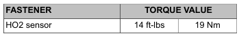
    6. Disconnect front and rear HO2 sensor connectors.

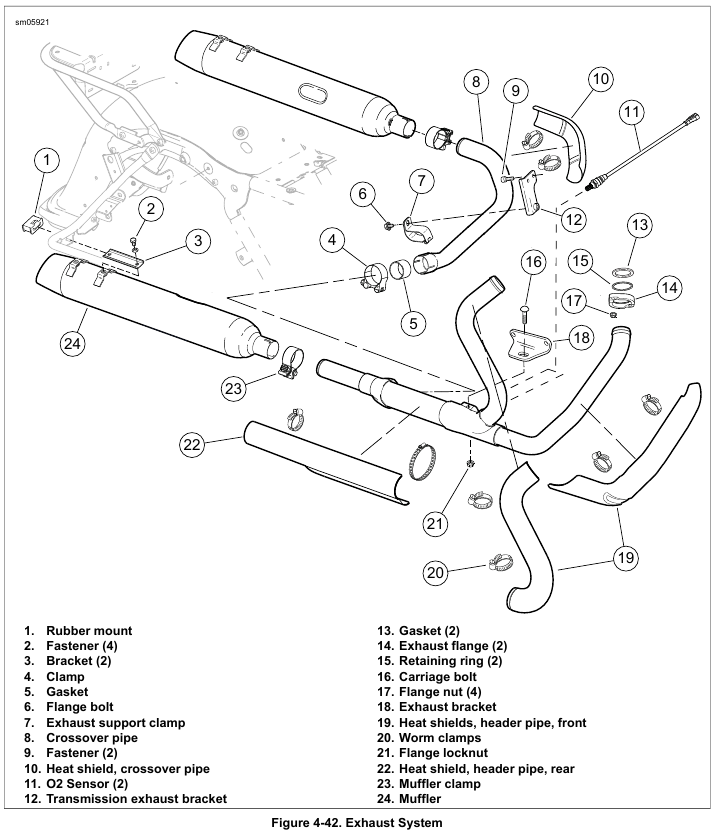
    7. See Figure 4-42. Remove heat shields (10, 19, 22) from pipes.

    NOTE

    Some models are equipped with only a single muffler on the right side.

    8. Loosen clamp (4).

    9. Remove fastener (6) and clamp (7).

    10. Pull and twist on crossover pipe to remove (8).

    11. Remove two flange nuts (17) to release front header pipe from studs of front cylinder head. Slide exhaust flange down header pipe to improve clearance around exhaust port.

    12. Remove two flange nuts (17) to release rear header pipe from studs of rear cylinder head.

    13. Remove flange nut (21) and carriage bolt (16).

    14. Remove exhaust header pipe.

    15. Remove and discard gaskets (13) from front and rear exhaust ports.

    16. Inspect retaining rings (15) and flanges (14). Replace as necessary.


  • 2015 Touring – EXHAUST SYSTEM – MUFFLERS

    Removal

    1. Remove saddlebags. See 2.31 SADDLEBAGS.

    2. See Figure 4-42. Remove two fasteners (2) and lockwashers.

    3. Loosen clamp (23).

    4. Pull and twist muffler to remove.

    5. Inspect rubber mount (1) for deterioration or damage. Replace as necessary.

    Installation

    1. Slide new muffler clamp onto muffler. Push muffler squarely onto exhaust pipe.

    2. Secure muffler to bracket (3) with fasteners (2) and lockwashers. Tighten to 14-18 ft-lbs (19.0-24.4 Nm).

    3. Tighten clamp (23) to 38-43 ft-lbs (51.5-58.3 Nm).

    4. Install saddlebags. See 2.31 SADDLEBAGS.


  • 2015 Touring – FUEL PUMP – FUEL PUMP AND FUEL LEVEL SENDER WIRE HARNESS

    Removal

    NOTE

    Damaged wiring, terminals and/or connectors requires replacement of the wire harness. Do not replace the special teflon coated wiring with ordinary bulk wire. Ordinary insulation materials may deteriorate when in contact with gasoline.

    1. Remove fuel pump. See 4.17 FUEL PUMP.

    2. Cut cable strap to release wire harness and both fuel pump and transfer tubes from arm of fuel pump bracket.

    3. Release wire harness from molded clip at front of fuel pump bracket.

    4. Remove connector at top of fuel pump.

    Installation

    1. Install connector at top of fuel pump.

    2. Route wire harness rearward and then forward under arm of fuel pump bracket. Install new cable strap at elbow capturing fuel pump and transfer tubes at top of arm and wire harness at bottom. See Figure 4-40.

    3. Route wire harness through molded clip at front of fuel pump bracket. See Figure 4-41.

    4. Install fuel pump. See 4.17 FUEL PUMP.


  • 2015 Touring – FUEL PUMP – INSTALLATION

    1. If removed, assemble fuel pump assembly:
    a. Reaching into fuel tank, capture transfer tube in weld clip on right side of tunnel.
    b. Install fuel inlet strainer to bottom of fuel pump.

    2. Install fuel pump into left side of fuel tank. Hold fuel pump assembly so that transfer tube connection is pointing rearward and insert into fuel tank. Rotate assembly 90 degrees counterclockwise.

    3. Look into fuel tank to verify that fuel inlet strainer lies flat and that ends are not folded under fuel pump. Also verify that wire harness is still captured in molded clip at front of fuel pump bracket.

    4. With the finger on the fuel pump bracket pointing rearward, engage four ears on bracket with rear set of catches at top of tunnel. Push fuel pump bracket rearward until ears are fully engaged.

    5. Install transfer tube onto transfer tube bracket. Fit two tabs at bottom of transfer tube bracket into slots at top of fuel pump bracket. Verify that transfer tube is still captured in weld clip on right side of tunnel. Verify that free end is in contact with bottom of fuel tank.

    6. Install fuel level sender. See 4.10 FUEL LEVEL SENDER.

    7. Install top plate. See 4.7 FUEL TANK TOP PLATE.

    NOTE

    The low fuel lamp will not turn off until there is sufficient fuel in the tank, the ignition switch has been turned off and back on, and the vehicle has begun forward movement.


  • 2015 Touring – FUEL PUMP – REMOVAL

    1. Remove top plate. See 4.7 FUEL TANK TOP PLATE.

    2. Remove fuel level sender. See 4.10 FUEL LEVEL SENDER.

    3.
    Pull up on transfer tube bracket to release two tabs at
    bottom from slots at top of fuel pump bracket.

    4. Press collar on each side of fitting to disconnect transfer tube from transfer tube bracket.

    5. See Figure 4-38. Pull up on rear finger and slide fuel pump bracket forward until four ears on bracket are free of catches at top of tunnel.

    6. See Figure 4-39. Remove fuel pump from left side of fuel tank. Rotate fuel pump assembly 90 degrees clockwise until transfer tube connection is pointing rearward. Remove from fuel tank.

    7. If necessary, further disassemble fuel pump assembly :
    a. Reaching into fuel tank, release transfer tube from weld clip on right side of tunnel and remove from fuel tank.
    b. Press arms on fuel inlet strainer and remove from slots in fuel pump housing.
    c. Inspect the condition of the fuel pump wiring. If the wiring needs to be replaced, see 4.17 FUEL PUMP, Fuel Pump and Fuel Level Sender Wire Harness.


  • 2015 Touring – FUEL PUMP – GENERAL

    When servicing the fuel system, do not smoke or allow open flame or sparks in the vicinity. Gasoline is extremely flammable and highly explosive, which could result in death or serious injury. (00330a)

    Do not use solvents or other products that contain chlorine on plastic fuel system components. Chlorine can degrade plastic fuel system components, which can cause a loss of fuel system pressure or engine stalling and could result in death or serious injury. (000621b)

    Carefully inspect tubes for damage. Even a small hole can cause a reduction in fuel pressure. Replace fuel pump as necessary.

    See the electrical diagnostic manual for information on the function and testing of the fuel pump.


  • 2015 Touring – FUEL INJECTORS – INSTALLATION

    1. Apply a very light film of clean engine oil to new O-rings.
    Install O-rings on fuel injectors.

    2. Push open end of fuel injectors (opposite cone spray) into fuel rail.

    3. Rotate fuel injectors until the electrical connectors are on the outboard side. Push cone spray end of fuel injectors into bores of induction module until slot at bottom of fuel rail engages machined tab at top of induction module.

    4. Install new O-ring and sealing washer in fuel rail bore.
    Install second O-ring and second sealing washer.

    5. Push fuel supply tube into fuel rail bore.

    6. Rotate fuel supply tube clockwise until tapered end of quick connect fitting is pointing upward. Now rotate tube an additional 90 degrees until fitting is pointing rearward (toward TCA on induction module).

    7. Engage slot on fuel supply tube clamp in groove of fuel supply tube fitting. Rotate fuel supply tube clamp 90 degrees counterclockwise until curled lip on fuel supply tube clamp engages flange on fuel rail.

    8. Secure fuel rail and fuel supply tube clamp to induction module with screw. Tighten to 66-82 in-lbs (7.5-9.3 Nm).

    9. Install induction module. See 4.13 INDUCTION MODULE.


  • 2015 Touring – FUEL INJECTORS – REMOVAL

    1. Remove induction module. See 4.13 INDUCTION MODULE.

    2. Remove screw to release fuel supply tube clamp from fuel rail.

    3. See Figure 4-37. Rotate fuel supply tube clamp 90 degrees clockwise. Remove from groove in fuel supply tube fitting.

    4. Pull fuel supply tube from fuel rail bore and remove two O-rings and two sealing washers. Discard O-rings and sealing washers.

    5. Pull fuel injectors with attached fuel rail from induction module. Gently rock assembly back and forth while pulling.

    6. Remove fuel injectors from fuel rail.

    7. Remove O-rings from fuel injectors. Discard O-rings.


  • 2015 Touring – FUEL INJECTORS – GENERAL

    Stop the engine when refueling or servicing the fuel system. Do not smoke or allow open flame or sparks near gasoline. Gasoline is extremely flammable and highly explosive, which could result in death or serious injury. (00002a)

    Do not use solvents or other products that contain chlorine on plastic fuel system components. Chlorine can degrade plastic fuel system components, which can cause a loss of fuel system pressure or engine stalling and could result in death or serious injury. (000621b)

    See the electrical diagnostic manual for information on the function and testing of the fuel injectors.


  • 2015 Touring – HEATED OXYGEN SENSORS (HO2) – INSTALLATION

    NOTES

    • Do not install sensors that have been dropped or impacted by other components. The sensing element may be damaged.
    • Replacement sensor assemblies have threads coated with anti-seize lubricant and a new gasket.
    • If HO2 sensor will be reused, replace the gasket. Use highquality professional grade sidecutters for gasket removal.
    • If HO2 sensor will be reused, apply a thin coat of ANTISEIZE LUBRICANT to threads of each sensor prior to installation. Do not use any other grease or sealant product on sensor threads.
    • The electrical connector must be clean and free of any dielectric grease.

    1. If reusing HO2 sensor:
    a. Remove used seal. Install a new one.
    b. Apply a light coating of ANTI-SEIZE LUBRICANT to threads.

    2. Using OXYGEN SENSOR WRENCH (Part No. HD-50017), install oxygen sensor. Tighten to 14 ft-lbs (19 Nm).

    3. See Figure 4-36. Route harness along lower frame and above the rear engine mount. Secure in harness retainer (5).

    NOTE

    Verify connector halves are clean and free of grease or other contaminants. NEVER apply dielectric grease, cleaning agents or any other lubricants, sealants or fluids to HO2 sensor connectors. Any such application will result in corrupted signals and sensor failure.

    4. Connect sensor connector (1 or 2). Secure sensor harnesses with new cable straps to rear frame down tube (3) and brake hose (4).

    5. Install main fuse. See 7.3 SYSTEM FUSES AND RELAYS.