Author: Sam

  • 2015 Touring – FUEL LEVEL SENDER – REMOVAL

    1. Remove top plate. See 4.7 FUEL TANK TOP PLATE.

    2. Disconnect 2-place connector to release fuel level sender from wire harness.

    NOTE

    See Figure 4-21. Look into fuel tank at bracketry. Note that finger (1) on front bracket points forward, while finger on rear bracket points rearward.

    3. Pull up on front finger (1) and slide fuel level sender bracket rearward until four ears on bracket are free of catches at top of tunnel.

    4. Remove fuel level sender from left side of fuel tank. See Figure 4-22.


  • 2015 Touring – FUEL PRESSURE REGULATOR – INSTALLATION

    1. See Figure 4-20. Insert small O-ring at top of pressure port bore.

    2. Install screen at top of pressure regulator bore, so that sleeve on ID faces small O-ring. Install regulator seat to evenly press screen into bore. Remove regulator seat.

    3. Install large O-ring at top of screen.

    4. Install regulator seat and fuel pressure regulator.

    5. Install spring clip, so that indented sides engage top of center rib on fuel pressure regulator, while rounded side engages bottom of tabs on housing.

    6. Route ground wire around index pin side of end cap and install spade terminal into slot in fuel filter shell.

    7. Install top plate. See 4.7 FUEL TANK TOP PLATE.


  • 2015 Touring – FUEL PRESSURE REGULATOR – REMOVAL

    1. Remove top plate. See 4.7 FUEL TANK TOP PLATE.

    2. See Figure 4-19. Remove ground wire spade terminal from slot of fuel filter shell.

    3. Remove spring clip from fuel pressure regulator. For best results, free one side first and then the other.

    4. See Figure 4-20. Remove fuel pressure regulator, regulator seat, large O-ring, screen and small O-ring.


  • 2015 Touring – FUEL FILTER – INSTALLATION

    1. Install new filter in fuel filter shell.

    2. Seat O-ring on counterbore at top of filter.

    3. Install fuel filter shell over end cap, so that slot in fuel filter shell engages index pin on end cap.

    4. Holding parts together, slide U-clip through holes on locking arm side of fuel filter shell. Push U-clip until ends exit holes on opposite side. Retract U-clip until contact is made with step in locking arm.

    5. Route ground wire (from top plate TORX screw) around index pin side of end cap and install spade terminal into slot in fuel filter shell. Gently tug on wire to verify that ter- minal is locked.

    NOTE

    If terminal does not lock, use a thin blade to bend tang slightly away from terminal body.

    6. Install top plate. See 4.7 FUEL TANK TOP PLATE.


  • 2015 Touring – FUEL FILTER – REMOVAL

    1. Remove top plate. See 4.7 FUEL TANK TOP PLATE.

    2. Locate ground wire spade terminal in slot of fuel filter shell. Insert tip of small flat blade screwdriver through window to press tang, and then pull terminal from slot. See Figure 4-17.

    3. See Figure 4-18. Gently raise locking arm and pull U-clip (2) from holes in fuel filter shell.

    4. Remove fuel filter shell (1) from end cap.

    5. Remove O-ring (3) and filter (4) from fuel filter shell.


  • 2015 Touring – FUEL TANK TOP PLATE – INSTALLATION

    1. If installing a new top plate, first install fuel filter shell. See 4.8 FUEL FILTER.

    2. Inspect seal ring at bottom of top plate for damage. If necessary, install new seal ring with the nubs contacting the ring groove walls.

    3. See Figure 4-15. Verify retainers (3) are secure on fuel filter fittings, and that they are not damaged. Note that retainers are of different sizes to prevent improper assembly.

    4. Aligning latches and push tubes onto fittings of fuel filter shell until an audible click is heard. Pull on tubes to verify they are attached securely.

    5. Install connector at bottom of top plate.

    6. Route ground wire (from top plate connector) along inboard side of vapor valve and install spade terminal into slot in top plate.

    7. Install fuel tank top plate engaging index tab in slot at front of fuel tank collar.

    8. See Figure 4-16. Install cam ring over fuel tank top plate with the TOP stamp up.

    9. Engage CAM RING REMOVER/INSTALLER (Part No. HD-48646) in top plate. Push down on tool and rotate clockwise until each of four index tabs begin to engage slots in fuel tank collar.

    10. Install ratchet and rotate until cam ring is fully installed.

    NOTE

    See Figure 4-13. Always hold on to both the Cam Ring Remover/Installer and ratchet to prevent unexpected separation resulting in possible damage to the fuel tank.

    11. Install console. See 4.6 FUEL TANK, Console.

    12. Install seat. See 2.30 SEAT.

    13. Fill fuel tank. Carefully inspect for leaks. Start engine and repeat inspection.


  • 2015 Touring – FUEL TANK TOP PLATE – REMOVAL

    NOTE

    The gasoline in the fuel supply line is under high pressure (58 psi (400 kPa). To avoid an uncontrolled discharge or spray of gasoline, always purge the line before disconnecting.

    1. Relieve pressure from fuel system. See 4.6 FUEL TANK, Removal.

    2. Drain fuel from tank. Use a common pump or siphon and an approved gasoline storage container of sufficient capacity.

    3. Remove console. See 4.6 FUEL TANK, Console.

    4. See Figure 4-12. Remove cam ring using CAM RING REMOVER/INSTALLER (Part No. HD-48646) and raise top plate.

    NOTE

    See Figure 4-13. Always hold on to both the Cam Ring Remover/Installer and ratchet to prevent unexpected separation resulting in possible damage to the fuel tank.

    5. Remove connector at bottom of top plate using a small screwdriver.

    6. See Figure 4-14. Disconnect ground wire spade terminal from slot of top plate.

    7. See Figure 4-15. Press tabs on fuel line retainers (3) to remove lines from fittings on fuel filter shell.

    8. If top plate replacement is necessary, remove fuel filter shell. See 4.8 FUEL FILTER.


  • 2015 Touring – FUEL TANK – FUEL SUPPLY CHECK VALVE/TUBE

    Removal

    NOTE

    The in-tank check valve is housed in the quick-connect fitting. The check valve prevents the fuel tank from draining when the external supply line is disconnected.

    1. Remove top plate. See 4.7 FUEL TANK TOP PLATE.

    2. Pull up on chrome sleeve and pull down on fuel supply line fitting to disconnect fuel line from tank.

    3. See Figure 4-10. Loosen quick-connect fitting.

    4. Remove the fitting and fuel supply tube from fuel tank.

    Installation

    NOTE

    Carefully inspect fuel supply tube for damage. Replace as necessary.

    1. See Figure 4-11. Apply a light film of clean engine oil to new O-ring. Slide O-ring into groove of quick-connect fitting.

    2. Feeding fuel supply tube through hole at bottom of fuel tank, turn quick-connect fitting into bore.

    3. Tighten fitting to 22-26 ft-lbs (29.8-35.3 Nm).

    4. Install top plate. See 4.7 FUEL TANK TOP PLATE.

    5. Connect quick-connect fitting to fuel tank. While pushing up on bottom of fitting, pull down on chrome sleeve. Tug on fuel line fitting to verify that it is locked in position.


  • 2015 Touring – FUEL TANK – VENT TUBE: MODELS WITHOUT EVAP SYSTEM

    Removal

    1. Remove seat. See 2.30 SEAT.

    2. Remove console. See 4.6 FUEL TANK, Console.

    3. See Figure 4-9. Remove vapor tube from fitting (1) on fuel tank top plate.

    4. Remove two cable straps (4) securing tube to rear frame downtube.

    5. Remove tube.

    6. Inspect for deterioration, chaffing or other damage.
    Replace as necessary.

    Installation

    1. See Figure 4-9. Route tube down along inner side of rear left downtube. Install two cable straps (4) to secure to frame.

    2. Route line along center of fuel tank and connect to fitting (1) on fuel tank top plate.

    3. Install console. See 4.6 FUEL TANK, Console.

    4. Install seat. See 2.30 SEAT.


  • 2015 Touring – FUEL TANK – INSTALLATION

    1. Place fuel tank onto frame backbone and start front fuel tank fasteners.

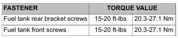
    2. Secure rear fuel tank bracket to frame backbone with two screws. Tighten to 15-20 ft-lbs (20.3-27.1 Nm). If removed, install plastic trim cover over bracket.

    3. Tighten front fuel tank screws to 15-20 ft-lbs (20.3-27.1 Nm). Install rubber caps over screws. Left and right caps
    are not interchangeable.

    To prevent spray of fuel, be sure quick-connect fittings are properly mated. Gasoline is extremely flammable and highly explosive, which could result in death or serious injury. (00268a)

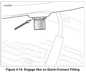
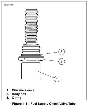
    4. Connect quick-connect fitting to fuel tank. While pushing up on bottom of fitting, pull down on chrome sleeve. After completing installation, tug on fuel line fitting to verify that it is locked in position.

    5. Road King Models: Mate fuel gauge connector. Feed connector into tunnel at front of fuel tank.

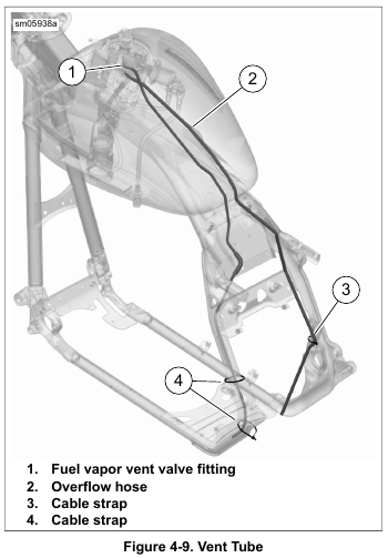
    6. See Figure 4-9. Connect fuel vapor vent tube to vapor valve fitting (1) on top plate.

    7. If equipped, connect overflow hose (2) to top plate and route along inner downtube as shown. Secure to brake line with cable strap (3). Do not over-tighten cable strap.

    8. Install fuel level sender/fuel pump connector [141], 4-place Delphi. For best clearance with cam ring, tilt connector at 35 degree angle before installation.

    9. Install console. See 4.6 FUEL TANK, Console.

    10. Install seat. See 2.30 SEAT.

    11. Install main fuse, left side cover and saddlebag.

    NOTE

    The low fuel lamp will not turn off until there is sufficient fuel in the tank, the ignition switch has been turned off and back on, and the vehicle has begun forward movement.