Author: Sam

  • 2015 Touring – FUEL PRESSURE TEST – GENERAL

    Improper fuel system pressure may contribute to one of the following conditions:
    • Cranks, but will not run.
    • Cuts out (may feel like ignition problem).
    • Hesitation, loss of power or poor fuel economy.

    See the electrical diagnostic manual for further information on the function and testing of the fuel system.

  • 2015 Touring – FASTENER TORQUE VALUES – FASTENER TORQUE VALUES IN THIS CHAPTER

    The table below lists torque values for all fasteners presented in this chapter.

  • 2015 Touring – OIL PAN – INSTALLATION

    1. See Figure 3-140. Clean and examine transmission and oil pan flanges.

    2. If removed, install tapered plug (4) using LOCTITE 565 THREAD SEALANT. Tighten to 18-22 ft-lbs (24.4-29.8
    Nm).

    3. Apply a thin coat of HYLOMAR GASKET AND THREAD SEALANT® gasket sealer to oil pan flange.

    4. Place new gasket (1) on oil pan flange. Allow sealer to dry until tacky.

    NOTE

    If oil pan fasteners are to be reused, apply 1-2 drops of LOCTITE 243 MEDIUM STRENGTH THREADLOCKER AND SEALANT (blue). New fasteners have a lock patch applied.

    5. Position oil pan with gasket on bottom of transmission and loosely install fasteners (6).

    6. Verify the gasket is properly positioned and tighten oil pan fasteners (6) to 132-156 in-lbs (14.9-17.6 Nm) following sequence shown in Figure 3-141.

    7. Clean engine and transmission drain plugs. Replace Orings as required.

    8. Install transmission drain plug and O-ring (5). Tighten to 14-21 ft-lbs (19.0-28.5 Nm).

    9. Install engine oil drain plug and O-ring (3). Tighten to 14-21 ft-lbs (19.0-28.5 Nm).

    10. Install exhaust crossover pipe hanger bracket and tighten fasteners to 100-120 in-lbs (11.3-13.6 Nm).

    11. Install exhaust crossover pipe and left muffler. See 4.18 EXHAUST SYSTEM.

    12. Install rear wheel. See 2.5 REAR WHEEL.

    13. Add fluids.
    a. Add transmission fluid and check level. See 1.11 TRANSMISSION LUBRICANT.
    b. Install engine oil filter. Add engine oil and check level. See 1.6 ENGINE OIL AND FILTER.


  • 2015 Touring – OIL PAN – REMOVAL

    1. Position motorcycle on a suitable lift.

    2. See Figure 3-140. Remove the engine oil drain plug (3), fill plug/dipstick and oil filter. Drain oil into suitable container.

    3. Remove the transmission drain plug (5) and drain transmission fluid into suitable container.

    4. Remove the rear wheel. See 2.5 REAR WHEEL.

    5. Remove the left muffler, exhaust crossover pipe and crossover pipe clamp bracket from the transmission. See 4.18 EXHAUST SYSTEM.

    6. See Figure 3-140. Remove 12 fasteners (6) that secure the oil pan to the transmission.

    NOTE

    Always remove the engine oil fill plug/dipstick to prevent damage during oil pan removal.

    7. Slide oil pan (2) rearward to remove. Remove and discard oil pan gasket (1).

    8. If necessary, remove tapered plug (4).

    9. Thoroughly inspect and clean the oil pan, especially if there was a major engine failure. Debris that remains in the pan will cause a repeat failure. Install a new oil pan if necessary.


  • 2015 Touring – CRANKCASE ASSEMBLY – CRANKCASE ASSEMBLY

    1. Secure left crankcase half upright in engine stand.

    2. Slide CRANKSHAFT GUIDE (Part No. HD-42326-B) onto flywheel sprocket shaft.

    3. Slide flywheel assembly into left crankcase half. Remove crankshaft guide tool.

    4. Rotate crankcase assembly so flywheel sprocket shaft is pointing straight up.

    5. Verify that both dowel pins are installed in split line face of right case half.

    6. Apply a bead of HIGH-PERFORMANCE SEALANT, GRAY (Part No. 99650-02) approximately 0.056 in. (1.42 mm) wide to the split line face and around the two dowel pins of right crankcase half.

    7. See Figure 3-137. Place CRANKSHAFT GUIDE (Part No. HD-42326-B) over end of crankshaft until it contacts shoulder on shaft.

    8. Mate case halves. Remove crankshaft guide.

    9. See Figure 3-138. Start the nine crankcase bolts and tighten in the following sequence.
    a. Finger-tighten each crankcase bolt.
    b. Tighten the crankcase bolts to 120 in-lbs (13.6 Nm) in the order shown.
    c. Following the same sequence, tighten each bolt to 15-19 ft-lbs (20.3-25.8 Nm).

    10. Rotate crankcase assembly so sprocket shaft is pointing straight up.

    11. Apply a liberal amount of SCREAMIN’ EAGLE ASSEMBLY LUBE to the main bearing. Rotate flywheel assembly to distribute lube.

    12. Install thrust washer on sprocket shaft with “THIS SIDE OUT” facing out (and the chamfer inboard). If using original part without markings, orient as required to preserve existing wear pattern.

    13. See Figure 3-139. Install new oil seal into bearing bore.
    Obtain pilot adapter, pilot shaft, short collar, bearing, large flat washer and handle from SPROCKET SHAFT BEARING INSTALLER (Part No. HD-97225-55C).
    a. Thread pilot adapter into sprocket shaft.
    b. Thread pilot shaft onto pilot adapter.
    c. Verify that lip garter spring is in place on both sides of oil seal.
    d. Install sprocket shaft spacer in oil seal bore.
    e. With the lettering on the oil seal facing outward, slide sprocket shaft spacer and oil seal over pilot shaft until it contacts bearing bore.
    f. Slide SPROCKET SHAFT OIL SEAL INSTALLER (Part No. HD-39361-B) over pilot shaft until it contacts oil seal.

    NOTE

    Sparingly apply graphite lubricant to threads of pilot shaft to prolong service life and provide smooth operation.

    g. Slide short collar, bearing and large flat washer onto pilot shaft. Thread handle on to complete assembly of tool.

    14. Rotate handle clockwise until oil seal installer makes firm contact with crankcase stator mount.

    15. Remove tool components from sprocket shaft.

    16. Rotate crankcase in engine stand so cam cover flange is facing upward.

    17. Apply a liberal amount of SCREAMIN’ EAGLE ASSEMBLY LUBE to the main bearing. Rotate flywheel assembly to distribute lube.

    18. Install oil pump and cam support plate. See 3.26 CAM COMPARTMENT AND COMPONENTS.

    19. Complete engine assembly.


  • 2015 Touring – FLYWHEEL AND CONNECTING RODS – MEASURING CRANKSHAFT RUNOUT

    Crankshaft Installed

    NOTES

    • Perform the following checks during engine disassembly as a method to determine condition of crankshaft and whether crankshaft is suitable for reuse. The checks can be done with the engine either installed in the frame or removed.

    • Dial indicators must be set up and zeroed perpendicular to the shaft in both directions. The indicator must be 90 degrees when viewed from the end and from the side.

    • For a reliable reading, only measure on the cam support plate bushing machined surface of the crankshaft, never on a shaft adapter or the bolt holes.

    • Never secure the dial indicator base to the vehicle frame. Movement within the engine mounts will result in a false reading.

    • While rotating the crankshaft, the indicator needle may move to both the minus and plus sides of zero. The total indicator reading is the value to record.

    1. Right Side
    a. Remove spark plugs.
    b. Remove the cam support plate. See 3.26 CAM COMPARTMENT AND COMPONENTS.
    c. Secure a dial indicator base to a stable location (crankcase, engine stand, etc.).

    NOTE

    To obtain an accurate measurement, the dial indicator must be set up perpendicular in both directions to the shaft being measured.

    d. Attach a dial indicator and set it up to measure runout at the cam plate bearing contact area of the crankshaft. Adjust the indicator to zero.
    e. Slowly rotate the crankshaft one complete revolution and record the total needle movement.
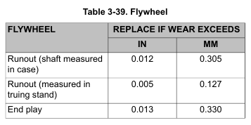
    f. Compare results of measurements. If the total indicator reading exceeds service wear limit, the crankshaft/flywheel assembly should be removed and checked on a truing stand. Refer to Table 3-39.

    2. Left Side
    a. Remove spark plugs.
    b. Remove the primary cover and compensating sprocket. See 5.4 DRIVE COMPONENTS.
    c. Secure a dial indicator base to a stable location (crankcase, engine stand, etc.).

    NOTE

    To obtain an accurate measurement, the dial indicator must be set up perpendicular in both directions to the shaft being measured.

    d. Attach a dial indicator set up to measure runout near the end of the splined area of the crankshaft. Adjust the indicator to zero on the “high” part of one spline.

    e. Mark the crankshaft and crankcase to use as reference for the amount of rotation.

    NOTE

    Pay attention to only the values from the “high” part of the splines.

    f. Slowly rotate the crankshaft one complete revolution and record the total needle movement.

    g. Compare results to Table 3-39. If the total indicator reading exceeds service wear limit, remove the crankshaft/flywheel assembly and check on a truing stand.

    Crankshaft Removed

    NOTES

    • The following procedure should be performed if the crankshaft/flywheel assembly is suspected of being out of-true.
    • The crankshaft must be supported by the bearing races during inspection. Never use centers as the holes may not be perfectly centered.
    • Verify that the bearing races are in good condition and suitable for performing this inspection.

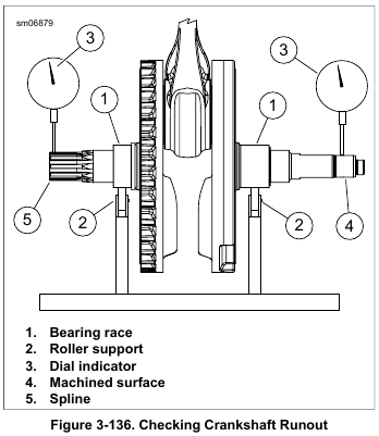
    1. See Figure 3-136. Mount crankshaft in truing stand so it is supported on the bearing races (1) by the roller supports (2).
    2. Secure a dial indicator mount near each end of the crankshaft.

    NOTE

    Dial indicators must be perpendicular to the shaft in both directions.

    3. Set up each indicator (3) to measure the machined surface (4) on one end and splines (5) on the other.

    4. Adjust both indicators to zero.

    5. Slowly rotate the crankshaft assembly while observing the total indicator reading.

    NOTE

    Twin Cam crankshaft/flywheel assemblies are not serviceable.
    Replace parts not within specifications.

    6. Compare results of measurements. If the total indicator reading exceeds service wear limit, replace the crankshaft/flywheel assembly. Refer to Table 3-39.


  • 2015 Touring – FLYWHEEL AND CONNECTING RODS – INSPECTION

    NOTE

    Do not attempt to straighten connecting rods. Straightening rods will damage both the upper bushing and lower bearing.

    1. Replace the flywheel/connecting rod assembly if any of the following conditions are noted:
    a. Connecting rods are bent or twisted.
    b. Connecting rods do not fall under their own weight or are in a bind.
    c. Sprocket teeth are worn in an irregular pattern or chipped.
    d. The crankshaft (roller) bearing inner races are brinelled, burnt, scored, blued or damaged.
    e. The crankshaft runout exceeds specification.

    NOTE

    Bluing on connecting rods is part of the hardening process and is considered a normal condition.

    2. Check connecting rod bearing clearance. Orient the assembly as shown in Figure 3-135.
    a. Holding the shank of each rod just above the bearing bore, pull up and down on the connecting rods.
    b. Any discernible up and down movement indicates excessive lower bearing clearance. Replace the flywheel/connecting rod assembly.

    3. Measure crankshaft runout if the crankshaft is suspected of being out-of-true.

    NOTE

    If the flywheel, connecting rods or right side bearing inner race need to be replaced, then replace the entire flywheel assembly.


  • 2015 Touring – FLYWHEEL AND CONNECTING RODS – GENERAL

    Symptoms

    Flywheels that shift out of true at the crank pin generally exhibit one of two symptoms: no oil pressure or vibration. This condition is also known as scissored flywheels.

    No Oil Pressure

    When the crankshaft shifts more than 0.015 in (0.381 mm), it can break the oil pump gerotors, resulting in a loss of oil pressure.

    If a very low or no oil pressure condition is confirmed, inspect the oil pump and cam support plate. If the oil pump gerotors are bound or damaged, the cause is likely from a contaminant running through the pump or a shifted crankshaft. If this type of damage is found, always replace the oil lines and clean all debris from the oil pan or oil tank. See 1.26 TROUBLESHOOTING for general diagnostics of low oil pressure.

    Vibration

    Generally, left crankshaft runout must exceed 0.020 in. (0.508 mm) to be noticeable to the rider. It is much more likely that vibration issues will be resolved by following the checklist in 1.26 TROUBLESHOOTING.

    If correct chassis set-up has been verified and other items in 1.26 TROUBLESHOOTING have been eliminated, checking left crankshaft runout is appropriate.


  • 2015 Touring – CRANKCASE DISASSEMBLY AND REPAIR – PIPE PLUG AND OIL FITTINGS

    Removal

    See Figure 3-134. Turn pipe plug counterclockwise until free.

    Installation

    1. Apply LOCTITE 565 THREAD SEALANT to threads.

    2. Install pipe plug. Tighten to 120-144 in-lbs (13.6-16.3 Nm).