Removal
If reusing flywheel, remove bearing inner race and thrust washer as follows:
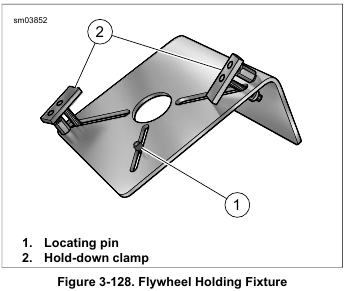
1. See Figure 3-128. Install brass jaws or shop towels around teeth of vise to prevent damage to tool. Obtain FLYWHEEL SUPPORT FIXTURE (Part No. HD-44358). Clamp tool in vise with the round hole topside.
2. Insert crankshaft end through hole resting flywheel assembly on fixture. Slide knurled locating pin down slot in tool to engage crank pin hole. Hand tighten locating pin.
3. Slide hold-down clamp down slot to engage inboard side of right flywheel half, and then hand tighten knurled nut at bottom to secure. Repeat step to secure hold-down clamp on opposite side of flywheel.
NOTE
For proper clamping force, hold-down clamp must not be tilted.
Rotate hex on outboard stud until clamp is level.
4. Position WEDGE ATTACHMENT (Part No. HD-95637-46B) on inboard side of thrust washer and turn hex nuts an equal number of turns to draw halves of wedge together.
5. Obtain two 3/8-16 inch bolts 7-1/2 inches long (with flat washers). Install flat washers on bolts. Obtain bridge and forcing screw from MAINSHAFT BEARING INNER RACE PULLER/INSTALLER (Part No. HD-34902-B). Also obtain a suitable hardened washer to use between the puller screw and the end of the shaft.
6. Slide one bolt into channel on each side of bridge so that flat washer is between bridge and bolt head. Thread bolts into wedge attachment an equal number of turns.
7. Sparingly apply graphite lubricant to threads of forcing screw to prolong service life and verify smooth operation.
Start forcing screw into center hole of bridge.
NOTE
Failure to use hardened washer may result in damage to forcing screw and/or sprocket shaft.
8. Place hardened washer against end of sprocket shaft. Thread forcing screw into bridge until the steel ball at the end of the screw makes firm contact with hardened washer.
9. Using the ROBINAIR HEAT GUN (Part No. HD-25070), uniformly heat the bearing inner race for about 30 seconds using a circular motion.
NOTE
To assist removal without heat, apply a light penetrating oil to shaft and leading edge of bearing inner race.
10. Turn forcing screw until thrust washer and bearing inner race move approximately 1/8 in. (3.2 mm).
11. Turn hex nuts an equal number of turns to separate halves of WEDGE ATTACHMENT (Part No. HD-95637-46B).
12. After bottoming thrust washer on shaft, reposition WEDGE ATTACHMENT (Part No. HD-95637-46B) on inboard side of bearing inner race. Turn hex nuts an equal number of turns to draw halves of wedge together.
Install wedge attachment only so far as necessary to ensure positive contact with bearing inner race. Installing tool with more contact than necessary will result in damage to the flywheel (00500b)
13. See Figure 3-129. Verify that the tool assembly is square, so that the bearing inner race is not cocked during removal.
14. Using the ROBINAIR HEAT GUN (Part No. HD-25070), uniformly heat the bearing inner race for about 30 seconds using a circular motion.
NOTE
To assist removal without heat, apply a light penetrating oil to shaft and leading edge of bearing inner race.
15. Turn forcing screw until bearing inner race is pulled free of sprocket shaft.
16. Remove thrust washer from sprocket shaft.

Installation
1. Place new thrust washer over sprocket shaft.
2. Place new bearing inner race on bench top. Using the ROBINAIR HEAT GUN (Part No. HD-25070), uniformly heat bearing inner race for about 60 seconds using a circular motion.
3. Wearing suitable gloves to protect hands from burns, place heated bearing inner race over sprocket shaft.
Do not use heating devices with penetrating oil. Penetrating oil is flammable which could result in death or serious injury. (00375a)
NOTE
To assist installation without heat, apply a light penetrating oil to shaft and leading edge of bearing inner race.
4. See Figure 3-130. Obtain the SPROCKET SHAFT BEARING INSTALLER (Part No. HD-97225-55C).
Assemble tool as described below.
a. See Figure 3-131. Thread pilot adapter into sprocket shaft.
b. Thread pilot shaft onto pilot adapter.
c. Slide long collar over pilot shaft until it contacts bearing inner race.
d. Slide short collar over pilot shaft until it contacts long collar.
e. Slide bearing and large flat washer over pilot shaft.
f. Sparingly apply graphite lubricant to threads of pilot shaft to prolong service life and verify smooth operation.
g. See Figure 3-132. Thread handle onto pilot shaft.
5. See Figure 3-133. Rotate handle of tool clockwise until bearing inner race makes firm contact with thrust washer.
Verify that thrust washer cannot be rotated by hand.
6. Remove handle, flat washer, bearing, short collar, long collar, pilot shaft and pilot adapter from sprocket shaft.