
Main Bearing Removal
NOTE
Never move or lift the crankcase by grasping the cylinder studs.
The crankcase is too heavy to be carried in this manner and may be dropped.
1. See Figure 3-123. Remove two main bearing retaining screws (5) from the cam compartment side.
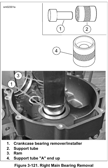
2. See Figure 3-121. Obtain CRANKCASE BEARING REMOVER/INSTALLER (Part No. B-45655) and REMOVER/INSTALLER SUPPORT TUBE (Part No. HD-42720-5)
3. Place support tube (4) on hydraulic press table with the “A” end up. Note that the sides of the support tube are stamped to verify proper orientation.
4. With the cam compartment side facing downward, position main bearing bore over support tube.
5. Slide remover/installer (1) through bearing into support tube.
6. Center remover/installer under ram (3) of press. Apply pressure until bearing is free.
7. Remove crankcase, remover/installer and bearing from support tube. Discard bearing.
Main Bearing Installation
1. See Figure 3-122. Obtain CRANKCASE BEARING REMOVER/INSTALLER (Part No. B-45655), CRANKSHAFT BEARING DRIVER SHIM (Part No. HD-42720-4) and REMOVER/INSTALLER SUPPORT TUBE (Part No. HD-42720-5).
2. Spread a thin film of clean engine oil on OD of new bearing (5).
3. Place support tube (3) on press table with the “B” end is up. The ends of the support tube are stamped “A” and “B” to verify proper orientation.
4. Place CRANKSHAFT BEARING DRIVER SHIM (Part No. HD-42720-4) (2) on support tube (3).
5. With the cam compartment side facing upward, position main bearing bore over support tube.
6. Start the new bearing in bearing bore with the lettering facing into the cam compartment (up).
7. Slide remover/installer (1) through bearing into support tube.
8. Center remover/installer under ram (4) of press. Apply pressure until resistance is felt and bearing is bottomed on the support tube.
9. Remove remover/installer and crankcase half from support tube.
NOTES
• Verify that the bearing is flush or slightly below the surface of the crankcase. Never “push” the bearing into position using the retaining screws.
• If new retaining screws are not available, apply LOCTITE 243 MEDIUM STRENGTH THREADLOCKER AND
SEALANT (blue) to threads of screws before installation.
10. See Figure 3-123. Install two new main bearing retaining screws (5) from the cam compartment side. Tighten screws to 40-70 in-lbs (4.5-7.9 Nm).

Piston Jets Removal
1. See Figure 3-123. Remove two screws (1) to free piston jet (2) from crankcase.
2. Remove O-ring (3) from groove in mounting flange of jet.
Discard O-ring.

Piston Jets Installation
NOTE
If piston jet is being reused, apply LOCTITE 222 LOW STRENGTH THREADLOCKER AND SEALANT (purple) to threads of screws before installation.
1. See Figure 3-123. Apply a very thin film of clean engine oil to new O-ring (3). Install new O-ring in groove of jet mounting flange.
2. With jet pointed upward, secure piston jet (2) with two screws (1). Tighten to 25-35 in-lbs (2.8-3.9 Nm).
Leave a Reply