Author: Sam

  • 2015 Touring – FUEL TANK – REMOVAL

    NOTE

    The fuel tank can be removed without draining. However, draining is necessary whenever the fuel tank or internal components are serviced.

    Purge and Disconnect Fuel Line

    NOTE

    The gasoline in the fuel supply line is under high pressure: 58 psi (400 kPA). To avoid an uncontrolled discharge or spray of gasoline, always purge the line before disconnecting.

    1. Remove seat. See 2.30 SEAT.

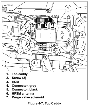
    2. See Figure 4-7. Disconnect fuel pump connector (gray) (4).

    3. Start the engine and allow the motorcycle to run until engine stalls. Operate starter an extra 3 seconds to remove remaining fuel from fuel supply line.

    4. Remove main fuse.

    5. Mate fuel pump connector (gray).

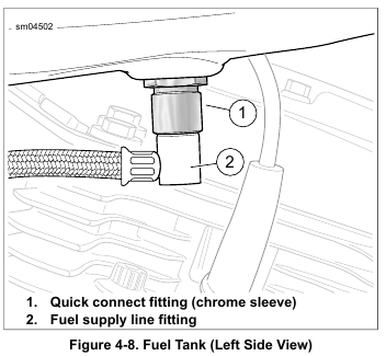
    6. See Figure 4-8. Pull up on chrome sleeve of quick-connect fitting and pull down on fuel supply line fitting to disconnect.

    Remove Tank

    1. Remove console. See 4.6 FUEL TANK, Console.

    2. Carefully remove fuel vapor vent tube from vapor valve fitting on top plate.

    3. Remove fuel level sender/fuel pump connector [141] from top plate.

    4. Road King Models: Draw fuel gauge connector out of tunnel under fuel tank. Separate connector.

    5. Remove rubber caps from front fuel tank screws. Remove screws.

    6. Remove two screws to release rear tank bracket from frame backbone.

    7. Remove fuel tank.


  • 2015 Touring – FUEL TANK – FUEL DOOR

    Door Replacement

    1. Remove screws securing hinge.

    2. Separate door from hinge. Remove door.

    3. Apply a drop of LOCTITE 243 MEDIUM STRENGTH THREADLOCKER AND SEALANT (blue) to the treads of
    the screws.

    4. Secure door to hinge with screws. Tighten to 25-30 in-lbs (2.8-3.4 Nm).

    Lock Replacement

    1. Remove nut securing lock assembly.

    2. Remove lock assembly.

    3. Secure lock assembly with nut. Tighten to 30-40 in-lbs (3.4-4.5 Nm).


  • 2015 Touring – FUEL TANK – CONSOLE

    Removal

    1. See Figure 4-7. Separate fuel pump connector (4). Separate rider headset harness connector (5) if equipped.

    2. Remove screws to release front and rear of console from fuel tank.

    3. Road King Models: Remove console.

    4. All but Road King Models: Remove filler cap. Remove console.

    Installation

    1. Road King Models: Position console on fuel tank.

    2. All but Road King Models: Remove filler cap and position console on fuel tank. Install filler cap.

    3. Verify that harnesses and vent tube are not pinched.

    4. Install screws to fasten front and rear of console to fuel tank.
    a. Tighten front fastener to 20-30 in-lbs (2.3-3.4 Nm).
    b. Tighten rear fastener to 36-60 in-lbs (4.1-6.8 Nm).

    5. Mate connectors (4, 5).


  • 2015 Touring – AIR CLEANER ASSEMBLY – AIR CLEANER REPAIR

    Insert: With Screw Access

    1. See Figure 4-6. Remove air cleaner cover (3).

    2. Apply heat from a heat gun to inside of cover in area of cover insert (2).

    3. Remove old cover trim.

    4. Thoroughly remove all remaining adhesive from cover.

    5. Install new cover trim plate using supplied adhesive.

    Insert: Without Screw Access

    1. See Figure 4-6.Pull on front edge of insert (15) to remove.

    2. Remove old trim retainer material.

    3. Thoroughly remove all remaining adhesive from cover.

    4. Carefully align new decorative plate with retainer material attached. Press and hold in position on cover (3) for 10 seconds.

    NOTE

    Do not remove decorative plate for 24 hours.

    Snorkel

    1. See Figure 4-6. Pry bezel (14) off. A pry point is provided on the bottom of the bezel rim.

    2. Remove snorkel (12) from cover.

    3. Replace screen (13) if necessary.

    4. Assemble components back onto cover making sure that snorkel and bezel are securely mated.


  • 2015 Touring – AIR CLEANER ASSEMBLY – INSTALLATION

    1. See Figure 4-6. Install seal ring (11) on backplate (10).

    2. Install backplate with breather bolts (9). Tighten to 22-24 ft-lbs (29.8-32.5 Nm).

    3. Install breather tubes (8) onto breather bolts.

    NOTE

    Air cleaner mounting without installation of the breather tubes allows crankcase vapors to be vented into the atmosphere in violation of legal emissions standards.

    4. Install air filter and cover. See 1.7 AIR CLEANER AND EXHAUST SYSTEM.


  • 2015 Touring – AIR CLEANER ASSEMBLY – REMOVAL

    1. See Figure 4-6. Remove air cleaner cover and filter. See 1.7 AIR CLEANER AND EXHAUST SYSTEM.

    2. Remove breather tube (8) from fittings on breather bolts.

    3. Remove two breather bolts (9).

    4. Remove backplate (10).

    5. Remove seal ring (11) from backplate. Discard seal ring.

    Do not use gasoline or solvents to clean filter element. Flammable cleaning agents can cause an intake system fire, which could result in death or serious injury. (00101a)

    6. Inspect filter element. See 1.7 AIR CLEANER AND EXHAUST SYSTEM. Replace the filter element if damaged
    or if filter media cannot be adequately cleaned.


  • 2015 Touring – INTAKE LEAK TEST – PROCEDURE

    1. Run motorcycle until engine is at normal operating temperature.

    NOTE

    Do not direct propane stream toward air cleaner. Propane in the air cleaner creates false indicators.

    2. See Figure 4-5. Aim nozzle (3) toward possible sources of leak such as intake manifold mating surfaces.

    3. Press and release trigger button (2) to dispense propane. The tone of the engine changes when propane enters source of leak. Repeat as necessary to detect leak.

    4. When test is finished, close valve knob (turn knob fully clockwise).


  • 2015 Touring – INTAKE LEAK TEST – LEAK TESTER

    Parts List

    • Standard 14 oz propane cylinder.
    • PROPANE ENRICHMENT KIT (Part No. HD-41417).

    Tester Assembly

    1. See Figure 4-4. Make sure valve knob (6) is closed (fully clockwise).
    2. Install valve assembly (5) onto propane bottle (1).

    Tester Adjustment

    1. See Figure 4-4. Press and hold trigger button (8).
    2. Slowly open valve knob (6) until pellet in flow gauge (7) rises 5-10 SCFH on gauge.
    3. Release trigger button.

  • 2015 Touring – INTAKE LEAK TEST – GENERAL

    Do not allow open flame or sparks near propane. Propane is extremely flammable, which could cause death or serious injury. (00521b)

    Read and follow warnings and directions on propane bottle. Failure to follow warnings and directions can result in death or serious injury. (00471b)

    NOTES

    • To prevent false readings, keep air cleaner cover installed when performing test.

    • Do not direct propane into air cleaner. It will cause false readings.

    • Be careful when testing vehicle with Screamin’ Eagle air cleaner assembly. This type of air cleaner has an open backplate. Even with air cleaner cover on, directing nozzle too close to backplate can give false readings.


  • 2015 Touring – FUEL PRESSURE TEST – TESTING

    NOTE

    Avoid kinking the fuel supply line when installing/removing the fuel pressure gauge and adapters.

    1. Purge and disconnect fuel supply line. See 4.6 FUEL TANK, Removal. Leave the fuel pump connector separated.

    NOTE

    Use two fuel pressure gauge adapters to prevent twisting of the fuel supply line. Tug on all connections to verify they are secure.

    2. Install fuel pressure gauge adapters as follows:
    a. See Figure 4-1. Connect two FUEL PRESSURE GAUGE ADAPTER (Part No. HD-44061) together.
    b. Connect fuel line to adapter assembly.
    c. Connect adapter assembly to quick-connect fitting on fuel tank.

    3. Verify that the fuel valve and air bleed petcock on the FUEL PRESSURE GAUGE (Part No. HD-41182) are closed.

    4. See Figure 4-2. Connect fuel pressure gauge to Schroeder valve closest to the fuel tank.

    5. Mate fuel pump connector.

    6. Start and idle engine to pressurize the fuel system. Open the fuel valve.

    7. Position the clear air bleed tube in a suitable container and purge the gauge and hose of air. Close the petcock.

    8. Vary the engine speed and note the reading of the pressure gauge. Fuel pressure should remain steady at 55-62 psi (380-425 kPa).

    NOTE

    If the fuel pressure is not within specification, see the electrical diagnostic manual for further diagnosis.

    9. Turn off the engine. Purge the fuel pressure gauge of gasoline and remove fuel pressure gauge from Schroeder valve. Install protective cap.

    10. Remove adaptor fitting assembly from fuel supply line and quick-connect fitting on fuel tank.

    11. Connect fuel supply line fitting to fuel tank quick-connect. Tug on fuel supply line fitting to verify that it is secure.