Author: Sam

  • 2015 Touring – HEATED OXYGEN SENSORS (HO2) – REMOVAL

    1. Remove main fuse. See 7.3 SYSTEM FUSES AND RELAYS.

    2. See Figure 4-36. Cut cable straps (3, 4) and disconnect oxygen sensor connector (1 or 2).

    3. Release harness from retainer (5).

    4. Using OXYGEN SENSOR WRENCH (Part No. HD-50017), remove oxygen sensor (6).


  • 2015 Touring – TEMPERATURE MANIFOLD ABSOLUTE PRESSURE SENSOR (TMAP) – INSTALLATION

    1. Inspect O-ring on pressure port for cuts, tears or signs of deterioration. Install new O-ring if necessary.

    2. With the electrical connector facing toward the rear of the induction module, insert pressure port on TMAP sensor into hole in induction module.

    3. Align hole in TMAP sensor bracket with threaded hole in induction module.

    4. Install new hex screw and tighten to 58-64 in-lbs (6.6-7.2 Nm).

    5. Install fuel tank. See 4.6 FUEL TANK.


  • 2015 Touring – TEMPERATURE MANIFOLD ABSOLUTE PRESSURE SENSOR (TMAP) – REMOVAL

    1. Remove fuel tank. See 4.6 FUEL TANK.

    2. Remove hex screw to release TMAP sensor bracket from induction module. Discard screw.

    3. See Figure 4-35. While rotating TMAP sensor slightly, pull straight up to release pressure port from hole in induction module.


  • 2015 Touring – INDUCTION MODULE – INSTALLATION

    1. With the counterbore facing outward, slide flange adapters onto the induction module.

    2. Place a new seal in each flange adapter with the beveled side against the counterbore.

    3. See Figure 4-33. Slide induction module into position until slots engage screws on left side.

    4. Start right side screws. For best results, use the INTAKE MANIFOLD WRENCH (Part No. HD-47250).

    5. Loosely install two breather bolts to temporarily fasten mounting bracket to cylinder heads.

    6. Tighten right side flange adapter screws until snug. Tighten left side screws to 96-156 in-lbs (10.9-17.6 Nm).

    7. Tighten right side screws to 96-156 in-lbs (10.9-17.6 Nm).

    8. See Figure 4-33. Install rear fuel injector connector (6) and front fuel injector connector (1).

    9. Install TMAP sensor connector (5).

    10. Route TCA connector and harness straight down between induction module and front cylinder staying inboard of mounting bracket. Loosely capture TCA harness to hole at front right side of induction module with new anchored cable strap.

    11. Route conduit rearward under induction module and install TCA connector (4). Tighten cable strap. Remove excess cable strap material.

    12. Connect purge tube to fitting (2) (California models only). On non-California models, inspect rubber cap for damage. Replace cap if damaged or missing.

    13. Twin-Cooled models: Install upper coolant lines to cylinder heads. Fill and bleed cooling system. See C.5 COOLING SYSTEM REPAIR.

    14. Install ACR connector retainer on mounting bracket (3) and secure connectors to it.

    15. Install fuel tank. See 4.6 FUEL TANK.

    16. Install backplate and air cleaner. See 4.5 AIR CLEANER ASSEMBLY.


  • 2015 Touring – INDUCTION MODULE – REMOVAL

    1. Remove fuel tank. See 4.6 FUEL TANK.

    2. Remove air cleaner and backplate. See 4.5 AIR CLEANER ASSEMBLY.

    3. See Figure 4-33. Remove ACR connectors and retainer from mounting bracket (3).

    4. Twin-Cooled models: Drain coolant and remove upper coolant lines from cylinder heads. See C.5 COOLING SYSTEM REPAIR.

    5. California models only: Pull purge tube from fitting (2) at top of induction module.

    6. Remove TMAP sensor connector (5).

    7. Remove front fuel injector connector (1) and rear fuel injector connector (6).

    8. Remove TCA connector (4). Cut anchored cable strap to release connector conduit from front right side of induction module.

    9. Remove right side screws from front and rear cylinder head flange adapters. For best results, use the INTAKE MANIFOLD WRENCH (Part No. HD-47250). See Figure 4-34.

    10. Loosen left side screws from flange adapters. Slots in flanges make removal of screws unnecessary.

    11. Slide induction module out right side of motorcycle.

    12. Remove seals from flange adapters. Discard seals. Remove flange adapters from outlet ports of induction module.


  • 2015 Touring – THROTTLE CONTROL ACTUATOR (TCA) – GENERAL

    NOTE

    See Figure 4-32. The TCA is not sold separately. Failure requires replacement of the complete induction module. Tampering with or removing the TCA cover voids warranty.
    See the electrical diagnostic manual for information on the function and testing of the TCA.


  • 2015 Touring – TWIST GRIP SENSOR (TGS) – TWIST GRIP SENSOR JUMPER HARNESS

    Removal

    1. Remove twist grip sensor. See 4.11 TWIST GRIP SENSOR (TGS), Removal.
    2. See Figure 4-30. Securely attach chaser wire to jumper harness.
    3. Gently pull jumper harness out through slot at center of handlebar. Remove chaser wire from jumper harness.

    Installation

    1. Securely attach chaser wire to jumper harness. If equipped, secure heated handgrip connector to harness with electrical tape.

    2. Carefully draw connector and jumper harness through handlebar while feeding harness into handlebar.

    3. Remove chaser wire from jumper harness.

    4. Install twist grip sensor. See 4.11 TWIST GRIP SENSOR (TGS), Installation.

    5. See Figure 4-31. Secure TGS jumper harness to handlebar with new cable straps.


  • 2015 Touring – TWIST GRIP SENSOR (TGS) – INSTALLATION

    NOTE

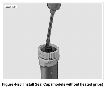
    See Figure 4-28. The seal cap protects the TGS terminals from dirt and moisture and also serves as a retention device for installation of the throttle grip.

    1. Verify that seal cap is installed at end of twist grip sensor.
    If seal cap is not present, it may remain inside throttle grip.
    a. Check condition of O-ring on seal cap. O-ring is only available as part of the seal cap assembly.
    b. See Figure 4-28. Install seal cap engaging legs in slots at end of twist grip sensor.

    2. Mate TGS connector to TGS jumper harness.

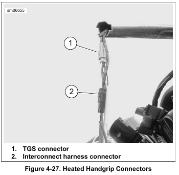
    3. Models with heated hand grips: See Figure 4-27. Mate the interconnect harness connector (2).

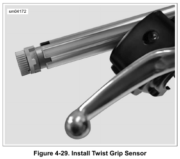
    4. See Figure 4-29. Gently draw jumper harness into handlebar while guiding TGS into end of handlebar. Align index tabs on twist grip sensor into slots in handlebar.
    Verify that the TGS is completely engaged into the slots in the handlebar.

    5. Position hand grip so any cosmetic features are properly positioned. Install the hand grip and rotate to verify that internal splines are engaged with the twist grip sensor.

    6. Models with heated hand grips: Install hand grip and connect heated hand grip connector.
    See 2.28 HANDLEBAR, Heated Hand Grips. Install end cap.

    NOTE

    Always follow the procedure in 7.37 HANDLEBAR SWITCH PACKS when installing right switch housing to be sure the twist grip operates correctly.

    7. Install switch housing and brake lever/master cylinder assembly. See 7.37 HANDLEBAR SWITCH PACKS.

    8. Connect TGS jumper harness connector.

    9. Road King models: Install handlebar clamp shroud and headlamp. See 2.47 HEADLAMP NACELLE: ROAD KING MODELS. Secure TGS harness and brake line to right handlebar riser with a new cable strap.

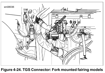
    10. Fork mounted fairing models:
    a. Rotate inner fairing. See 2.39 INNER FAIRING: FORK MOUNTED FAIRING MODELS, Rotate Inner Fairing.
    b. See Figure 4-24. Connect TGS connector.
    c. Install outer fairing.
    d. See Figure 4-31. Loop TGS jumper harness across handlebar. Secure with new cable straps (1).

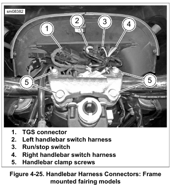
    11. Frame mounted fairing models:
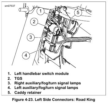
    a. See Figure 4-25. Connect TGS connector (1).
    b. Secure TGS harness with new cable strap.
    c. Install instrument bezel. See 2.40 INSTRUMENT BEZEL: FRAME MOUNTED FAIRING MODELS.

    12. If present, install two cable clips on handlebar switch harnesses into holes in handlebar.

    13. Install main fuse.

    NOTE

    Whenever a new TGS (or ECM) is installed, idle speed must be reset. The ECM uses the first four ignition cycles to establish the optimum idle speed. If the procedure is not performed, initial performance problems may result.

    • Place the engine run/stop switch in the RUN position.
    • Turn the ignition/light keyswitch to IGNITION and then back to OFF four times without starting engine. Allow at least three seconds to elapse between ignition cycles.


  • 2015 Touring – TWIST GRIP SENSOR (TGS) – REMOVAL

    1. Remove main fuse.

    2. Release the right switch housing and front brake control from the handlebar. See 7.37 HANDLEBAR SWITCH PACKS.

    3. Models with heated hand grips: Pry end cap from handgrip and pull connector out through end of hand grip.
    See 2.28 HANDLEBAR, Heated Hand Grips. It is not necessary to disconnect the heated hand grip power or interconnect connectors.

    NOTE

    To remove the hand grip, a slight tug may be necessary.

    4. Remove the hand grip from the end of the handlebar.

    5. If present, remove two harness retainers from holes in handlebar.

    NOTE

    The TGS jumper harness connector [204] is a 6-place Molex (black).

    6. Road King models: See Figure 4-23. Remove headlamp and handlebar clamp shroud. See 2.47 HEADLAMP NACELLE: ROAD KING MODELS. Disconnect TGS connector (2). Cut cable strap securing harness to right riser.

    7. Fork mounted fairing models:
    a. Remove outer fairing.
    b. See Figure 4-24. Disconnect TGS connector.
    c. Rotate inner fairing. See 2.39 INNER FAIRING: FORK MOUNTED FAIRING MODELS, Rotate Inner Fairing.
    d. See Figure 4-31. Cut cable straps securing harness to handlebar.

    8. Frame mounted fairing models:
    a. Remove instrument bezel. See 2.40 INSTRUMENT BEZEL: FRAME MOUNTED FAIRING MODELS.
    b. See Figure 4-25. Disconnect TGS connector (1).

    NOTE

    The internal TGS connector can break if the TGS is pulled too hard. The connector is not serviceable. Damage requires replacement of the TGS jumper harness or TGS assembly.

    9. Carefully pull TGS out of handlebar while feeding jumper harness into center of handlebar. Pull out only far enough to access the connectors.

    NOTE

    The latch on the pin housing is very fragile. Use care when releasing it. The connector is not serviceable and can only be obtained as part of the twist grip sensor jumper harness.

    10. See Figure 4-26. Gently insert a small flat blade screwdriver between pin and socket housings and separate housings. Do not pivot or rotate screwdriver after insertion or damage to pin housing may occur.

    11. See Figure 4-27. Models with heated hand grips: Separate the interconnect harness connector (2).

    12. Remove TGS.


  • 2015 Touring – FUEL LEVEL SENDER – INSTALLATION

    1. With the finger on the fuel level sender bracket pointing forward, install fuel level sender into left side of fuel tank.

    2. Engage four ears on fuel level sender bracket with front set of catches at top of tunnel. Push fuel level sender bracket forward until ears are fully engaged.

    3. Connect 2-place connector to attach fuel level sender to wire harness.

    4. Install top plate. See 4.7 FUEL TANK TOP PLATE.

    NOTE

    The low fuel lamp will not turn off until there is sufficient fuel in the tank, the ignition switch has been turned off and back on, and the vehicle has begun forward movement.