Author: Sam

  • 2015 Touring – EVAPORATIVE EMISSIONS CONTROL SYSTEM – PURGE SOLENOID

    Removal

    1. Remove seat. See 2.30 SEAT.

    2. Remove top electrical caddy and remove purge solenoid from caddy. Lay caddy aside. See 7.6 ELECTRICAL CADDIES.

    3. See Figure 4-49. Remove purge solenoid connector (1).

    4. Remove purge tubes (2, 3) from purge solenoid.

    5. Remove purge solenoid from motorcycle.

    Installation

    1. See Figure 4-49. Install purge tube to induction module (3) onto fitting of purge solenoid closest to the connector cavity.

    2. Install purge tube from charcoal canister (2) onto purge solenoid.

    3. Install purge solenoid connector (1).

    4. Secure solenoid to top caddy and install top caddy. See 7.6 ELECTRICAL CADDIES.

    5. Check all routing to be sure that tubes are not pinched or kinked, and that there is no contact with hot exhaust or engine parts.

    6. Install seat. See 2.30 SEAT.


  • 2015 Touring – EVAPORATIVE EMISSIONS CONTROL SYSTEM – SOLENOID-TO-INDUCTION MODULE TUBE

    Removal

    1. Remove seat. See 2.30 SEAT.

    2. Remove fuel tank. See 4.6 FUEL TANK.

    3. See Figure 4-48. Remove purge tube (3) from purge solenoid.

    4. Remove cable clip on purge tube from frame backbone.

    5. Disconnect tube from fitting on induction module.

    6. Remove purge tube.

    Installation

    1. Route purge tube rearward under frame crossmember and into area near purge solenoid, then along bottom of frame backbone toward induction module. Connect to fitting on induction module.

    2. See Figure 4-48. Route purge tube under frame crossmember and install on upper fitting (3) of purge solenoid.

    3. Secure purge tube to bottom of frame backbone with new retainer.

    4. Install fuel tank. See 4.6 FUEL TANK.

    5. Install seat. See 2.30 SEAT.


  • 2015 Touring – EVAPORATIVE EMISSIONS CONTROL SYSTEM – CANISTER-TO-SOLENOID TUBE

    Removal

    1. Remove seat. See 2.30 SEAT.
    2. See Figure 4-48. Remove purge tube (2) from fitting of purge solenoid and canister.

    Installation

    1. Install end of purge tube with curved hose onto lower fitting of canister.

    2. Install opposite end onto purge solenoid.

    3. Install seat. See 2.30 SEAT.

  • 2015 Touring – EVAPORATIVE EMISSIONS CONTROL SYSTEM – FUEL VAPOR VENT TUBE

    Removal

    1. Remove seat. See 2.30 SEAT.

    2. Remove console. See 4.6 FUEL TANK, Console.

    3. See Figure 4-46. Remove fuel vapor vent tube (6) from vapor valve fitting on fuel tank top plate (7).

    4. Disconnect vent tube from fitting on canister (9).

    5. Remove vapor vent tube from motorcycle.

    Installation

    1. See Figure 4-46. Connect fuel vapor vent tube (6) onto vapor valve fitting of fuel tank top plate (7).

    2. Connect vent tube to fitting on charcoal canister (9) marked “TANK”.

    3. Install console. See 4.6 FUEL TANK, Console.

    4. Install seat. See 2.30 SEAT.

  • 2015 Touring – EVAPORATIVE EMISSIONS CONTROL SYSTEM – VAPOR VALVE

    NOTE

    See Figure 4-47. The vapor valve is not serviceable. Damage or failure of the vapor valve requires replacement of the fuel tank top plate. See 4.7 FUEL TANK TOP PLATE.


  • 2015 Touring – EVAPORATIVE EMISSIONS CONTROL SYSTEM – GENERAL

    Motorcycles sold in some markets are equipped with an evaporative (EVAP) emissions control system. See Figure 4-46.

    The EVAP system functions as follows:

    • The fuel vapor vent tube is connected to the vent tube on the fuel tank top plate. It allows fuel vapors in the fuel tank to be vented to the charcoal canister.
    • Under certain engine conditions, the ECM (working in conjunction with the EFI system relay) opens the purge solenoid. Negative pressure (vacuum) draws the fuel vapors in the charcoal canister through the purge tube to the induction module. They are then burned as part of the normal combustion process.

    Keep evaporative emissions vent lines away from exhaust and engine. Gasoline is extremely flammable and highly explosive, which could result in death or serious injury. (00266a)

    NOTE

    The EVAP system has been designed to operate with a minimum of maintenance. Check that all tubes are correctly routed and properly connected. Also, verify that the tubes are not pinched or kinked. Verify that there is no contact between the tubes and engine parts.


  • 2015 Touring – ACTIVE EXHAUST: HDI – ACTIVE EXHAUST VALVE

    General

    The active exhaust valve is not repairable. Replace the rear exhaust header pipe if the valve is damaged or fails. See 4.18 EXHAUST SYSTEM.


  • 2015 Touring – ACTIVE EXHAUST: HDI – EXHAUST VALVE ACTUATOR CABLE

    Removal

    1. Remove exhaust valve actuator. See 4.19 ACTIVE EXHAUST: HDI, Exhaust Valve Actuator.

    2. Disconnect cable from exhaust valve:
    a. Push metal cable retainer off bracket on exhaust pipe.
    b. Release cable end from spool.

    3. See Figure 4-45. Cut cable strap (3). Release cable housing (2) from cable clip (1).

    Installation

    1. Install cable on exhaust valve:
    a. Install cable end into notch in exhaust valve spool.
    b. Push on metal cable retainer onto bracket on exhaust pipe.

    2. Install exhaust valve actuator. See 4.19 ACTIVE EXHAUST: HDI, Exhaust Valve Actuator.

    3. See Figure 4-45. Secure cable housing (2) in cable clip (1). Secure cable housing to brake line with cable strap (3).


  • 2015 Touring – ACTIVE EXHAUST: HDI – EXHAUST VALVE ACTUATOR

    Removal

    1. Remove right saddlebag and side cover.

    2. Remove right mid-frame air deflector. See 2.45 AIR DEFLECTORS.

    3. Disconnect electrical connector from actuator.

    4. See Figure 4-44. Remove two screws (4) and washers (3) to release active exhaust valve actuator (2) from right side caddy (1).

    5. Disconnect cable from actuator spool:
    a. Release plastic insert from actuator bracket.
    b. Release cable end from spool.

    6. Remove actuator.

    Installation

    1. Connect cable to actuator spool:
    a. Push cable end into hole in actuator spool until cable engages groove at center.
    b. Push to engage plastic insert in slot of actuator bracket.

    2. Secure active exhaust valve actuator to right side caddy with screws and washers. Tighten to 32-40 in-lbs (3.6-4.5 Nm).

    3. Mate electrical connector. Install mid-frame air deflector. See 2.45 AIR DEFLECTORS

    4. Verify cable is secured in anchor on rear frame downtube.

    5. Install right saddlebag and side cover.


  • 2015 Touring – EXHAUST SYSTEM – SYSTEM INSTALLATION

    1. See Figure 4-42. If removed, install transmission exhaust bracket (12) and tighten fasteners (9) to 100-120 in-lbs (11.3-13.6 Nm).

    2. Install new gaskets in both the front and rear cylinder head exhaust ports with the tapered side out.

    3. Place exhaust header pipe into position. Start two exhaust flange nuts to secure front header pipe to cylinder head.

    4. Roll pipe into position at rear cylinder with welded bracket on header pipe below the side exhaust bracket (18).

    5. Start two exhaust flange nuts to secure rear header pipe to studs of rear cylinder head.

    6. Secure header pipe to side exhaust bracket (18) with carriage bolt (16) and flange locknut (21). Do not tighten at this time.

    NOTE

    Some models are equipped with only a single muffler on the right side.

    7. Slide new clamp (4) onto crossover pipe.

    8. Install new gasket (5). Twist and push crossover pipe (8) onto exhaust header pipe.

    9. Install exhaust support clamp (7) and secure with fastener (6). Do not tighten.

    10. Install mufflers. See 4.18 EXHAUST SYSTEM, Mufflers.

    NOTES

    • Verify that the exhaust components do not contact the motorcycle frame or any mounted components.

    • Verify that no components are in a bind before and during tightening. This reduces the chance of unwanted noise or vibration.

    11. Tighten the exhaust system:
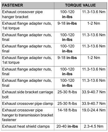
    a. Tighten the bottom nut of the rear cylinder exhaust flange to 9-18 in-lbs (1-2 Nm). Tighten the top nut to 100-120 in-lbs (11.3-13.6 Nm). Final tighten the bottom nut to 100-120 in-lbs (11.3-13.6 Nm).
    b. Tighten the top nut of the front cylinder exhaust flange to 9-18 in-lbs (1-2 Nm). Tighten the bottom nut to 100-120 in-lbs (11.3-13.6 Nm). Final tighten the top nut to 100-120 in-lbs (11.3-13.6 Nm).
    c. Tighten flange locknut (21) to 25-30 ft-lbs (33.9-40.7 Nm).
    d. Tighten crossover pipe clamp (4) to 25-30 ft-lbs (33.9-40.7 Nm).
    e. Tighten fastener (6) to 14-18 ft-lbs (19.0-24.4 Nm).

    NOTES

    • Verify that the heat shields do not contact the motorcycle frame or any mounted components.

    • See Figure 4-43. Install crossover pipe heat shield with the longer straight portion toward the muffler.

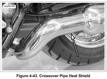
    12. Install heat shields. Position each worm drive clamp so that screw is on the outboard side in the most accessible position. Tighten to 20-40 in-lbs (2.3-4.5 Nm).

    13. Connect O2 sensor connectors and install new cable strap to secure leads to rear frame. Secure in harness retainer on lower frame.

    14. HDI models: connect cable to exhaust valve actuator:
    a. Install cable clip onto slotted flange at front of active exhaust valve.
    b. Push cam rearward and install ball end of cable into slot. Verify that cable is properly seated in channel of active exhaust valve.

    15. Install right side front footboard and brackets. See 2.52 FOOTBOARDS AND FOOTRESTS, Rider Footboards.

    16. Install seat. See 2.30 SEAT.

    17. Install saddlebags. See 2.31 SADDLEBAGS.