
1. See Figure 3-106. Apply a very thin film of SCREAMIN’ EAGLE ASSEMBLY LUBE to new O-ring (1) and install in groove around oil feed hole.
2. Lubricate cam needle bearings with SCREAMIN’ EAGLE ASSEMBLY LUBE.
3. See Figure 3-107. Verify that the timing marks on the ends of the front and rear camshafts are in alignment.


4. Slide cam support plate over crankshaft and onto two ring dowels in crankcase flange. Use a rubber mallet to fully seat cam support plate on ring dowels.
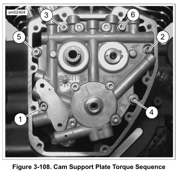
5. See Figure 3-108. Install cam support plate screws.
Tighten to 100-120 in-lbs (11.3-13.6 Nm) in the sequence shown.
NOTES
• Rotating the crankshaft while tightening screws will allow the oil pump to find its natural center. For methods of crankshaft rotation, see 3.18 TOP END OVERHAUL: DISASSEMBLY, Rocker Arm Support Plate.
• Numbers cast adjacent to the bolt holes indicate the oil pump torque sequence.
6. See Figure 3-109. Secure oil pump.
a. Start four screws to secure oil pump.
b. While rotating the crankshaft, install screws (1 and 2) until snug.
c. Install screws (3 and 4) until snug.
d. Tighten all four screws to 40-45 in-lbs (4.5-5.1 Nm) in the sequence shown.
e. Final tighten all four screws to 90-120 in-lbs (10.2-13.6 Nm) in the sequence shown.
7. With the lettering facing inboard, install rear cam sprocket spacer onto the rear camshaft.

8. Engines with one or more of the following new parts: cam support plate, camshafts, primary cam sprocket, crankshaft sprocket or flywheel assembly.
a. Install primary cam sprocket without chain using the long flange bolt with thicker flat washer.
b. Install crankshaft sprocket without chain using the short flange bolt and a smaller diameter flat washer from bulk inventory.
c. Position the CRANKSHAFT/CAMSHAFT SPROCKET LOCKING TOOL (Part No. HD-47941) between the crankshaft and primary cam sprockets. Tighten both sprocket flange bolts to 15 ft-lbs (20.3 Nm). Remove the sprocket locking tool.
d. Rotate engine stand so cam compartment is pointing upward. Push on crankshaft and rear camshaft to eliminate endplay.
e. If engine was not removed from motorcycle, install compensating sprocket assembly to pull the crankshaft to the left side of the engine. Push on crankshaft and rear camshaft to eliminate endplay.
f. See Figure 3-110. Place a straightedge across the sprocket faces. Attempt to insert a 0.010 in. (0.254 mm) feeler gauge between the straightedge and each sprocket face. If the feeler gauge will not fit at either location, sprocket offset is within specification.
Remove both sprockets and discard temporary small washer.
g. If measurement is not within specification, replace the rear cam sprocket spacer using Table 3-38 as a guide.
h. Repeat alignment inspection with the new spacer installed. Remove both sprockets when measurement is within specification and discard temporary small washer.


9. See Figure 3-111. Apply a light film of SCREAMIN’ EAGLE ASSEMBLY LUBE to splines on rear cam. Install the primary cam chain and sprocket assembly.
a. Place both cam sprockets (2, 4) in the primary chain with the timing marks aligned. Verify that the colored mark placed on the chain link (7) is on the same side as the timing marks and is visible during installation.
b. With the timing marks in alignment, start the rear cam sprocket onto the end of the rear camshaft. Note that the sprocket has an integral key that must be aligned with the keyway in the camshaft.
c. Maintaining the position of the crankshaft sprocket on the chain, rotate the rear cam sprocket clockwise until the flat on the crankshaft sprocket is aligned with the flat on the crankshaft. Install the crankshaft sprocket.
10. Rotate the crankshaft clockwise until the timing marks on the sprockets are aligned and also aligned with alignment mark (5) on cam support plate.
NOTES
• Both crank and rear cam sprocket flange bolts are specially hardened and the flat washers are of a special diameter.
• Use only genuine Harley-Davidson parts when replacement is necessary.
• If new flange bolts are not available, thoroughly clean both internal and external threads.
• Apply a small amount of LOCTITE 262 HIGH STRENGTH THREADLOCKER AND SEALANT (red) before installation.
• Both sprocket bolts must install freely by hand.
• The crankshaft and rear cam sprocket flange bolts and flat washers are not interchangeable.
• Refer to Table 3-38.
11. Apply a film of oil to bottom of both sprocket bolt heads and washers. Loosely install to secure sprockets.
12. Position the CRANKSHAFT/CAMSHAFT SPROCKET LOCKING TOOL (Part No. HD-47941) between the crankshaft and rear cam sprockets to prevent rotation.
The handle of the tool is stamped “Crank” and “Cam” to verify proper orientation.
a. Tighten both sprocket bolts (1, 3) to 15 ft-lbs (20.3 Nm).
b. Loosen both bolts one revolution (360 degrees).
c. Final tighten the rear cam sprocket bolt (1) to 34 ft- lbs (46.1 Nm).
d. Final tighten the crankshaft sprocket bolt (3) to 24 ft- lbs (32.5 Nm).
e. Remove the sprocket locking tool.
13. Install primary cam chain tensioner. Tighten to 100-120 in-lbs (11.3-13.6 Nm).
14. Apply SCREAMIN’ EAGLE ASSEMBLY LUBE to both sprockets.
NOTE
Inserting a screw into a blind hole with debris can damage the crankcase.
15. Clean all blind holes in crankcase.
16. See Figure 3-112. Install cam cover and new cam cover gasket.


17. See Figure 3-113. Secure cover with socket head screws.
Following the sequence shown, tighten the screws to 125-155 in-lbs (14.1-17.5 Nm).
18. If removed, install timer cover with five screws. Tighten to 20-30 in-lbs (2.3-3.4 Nm).
19.Complete motorcycle assembly.
a. If engine was completely overhauled, see 3.25 TOP END OVERHAUL: ASSEMBLY. Perform all steps.
b. If only cam compartment components were serviced, install pushrod covers, pushrods, rocker arm support plate and breather assembly. See appropriate topics under 3.25 TOP END OVERHAUL: ASSEMBLY.

Leave a Reply