NOTES
• Install the primary chain, compensating sprocket and clutch as a single unit.
• The O-ring inside the shaft extension is for manufacturing assembly only and has no replacement part.
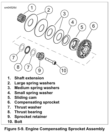
1. See Figure 5-9. Apply a thin layer of primary chaincase oil to the inner diameter of the compensating sprocket (6) and the splines of shaft extension (1). Install shaft extension.
NOTE
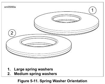
Outer diameter of spring washers must contact each other.
2. Install large spring washers (2) and medium spring washers (3).
3. Install small spring washer (4) so outer diameter will contact sliding cam (5).
4. Install the drive components (primary chain, compensating sprocket and clutch assembly).
5. Lightly lubricate thrust bearing (8). Install thrust washers (7), bearing (8), retainer (9) and new bolt (10). Hand tighten.
NOTE
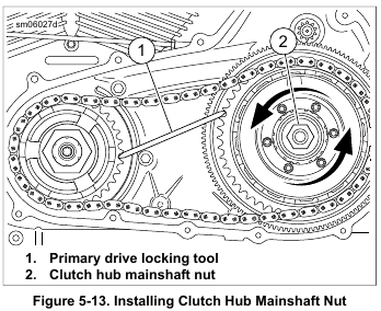
Clutch hub mainshaft nut has left-hand threads. Turn counter clockwise to install.
6. Clean and prime threads of clutch hub mainshaft nut. Apply two drops of LOCTITE 262 HIGH STRENGTH THREAD LOCKER AND SEALANT (red) to the threads. Start nut onto mainshaft. Hand-tighten.
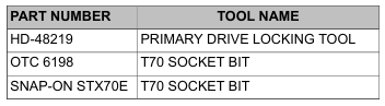
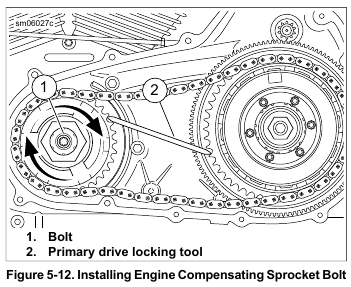
7. See Figure 5-12. Place the PRIMARY DRIVE LOCKING TOOL (Part No. HD-48219) between the teeth of the engine and clutch sprockets as shown.
NOTE
The compensating sprocket bolt is a T70 drive. Use T70 SOCKET BIT (Part No. Snap-on STX70E), T70 SOCKET BIT (Part No. OTC 6198) or equivalent.
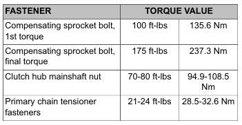
8. Tighten compensating sprocket bolt (1) to 100 ft-lbs (135.6 Nm).
9. Loosen one-half turn.
10. Final tighten to 175 ft-lbs (237.3 Nm).
11. See Figure 5-13. Install the PRIMARY DRIVE LOCKING TOOL (Part No. HD-48219) between the teeth of the engine and clutch sprockets as shown.
12. Tighten clutch hub mainshaft nut (2) to 70-80 ft-lbs (94.9-108.5 Nm). Remove primary drive locking tool.
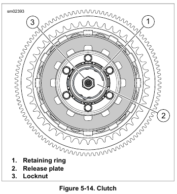
13. See Figure 5-14. Install release plate (2) with locknut (3) and adjuster screw into clutch hub bore. The word “OUT” stamped on the release plate faces out.
Wear safety glasses or goggles when removing or installing retaining rings. Retaining rings can slip from the pliers and could be propelled with enough force to cause serious eye injury. (00312a)
14. Inspect retaining ring (1) and replace if necessary. Install retaining ring in clutch hub bore. Verify the retaining ring is completely seated in the groove.
15. Adjust clutch. See 1.12 CLUTCH CABLE: ROAD KING, Adjustment.
NOTES
Primary chain tensioner is non-repairable. If tensioner is worn or damaged, replace assembly.
16. Tensioner parts can be disassembled. If primary chain tensioner becomes disassembled, assemble in order shown:
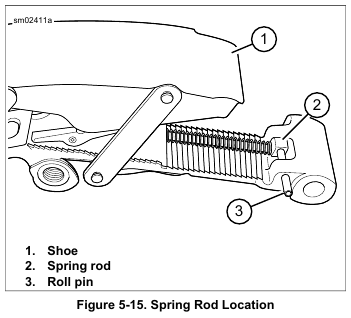
a. See Figure 5-15. Locate end of spring rod (2) on roll pin (3).
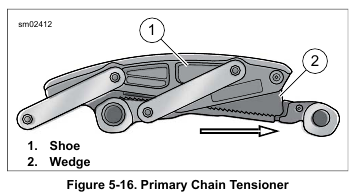
b. See Figure 5-16. Slide wedge (2) of primary chain tensioner in direction of arrow until all travel is removed.
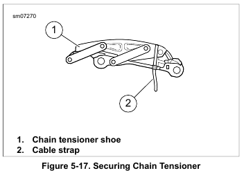
c. See Figure 5-17. Push shoe (1) down until it contacts wedge. Keep tension on shoe so wedge stays in place.
d. Insert cable strap (2) as shown to hold wedge in place.
Verify end of cable strap is located below primary chain tensioner. Cable strap will hang below primary cover gasket surface and serve as a reminder to remove before installing primary cover.
NOTE
Primary chain tensioner will not complete chain adjustment until vehicle is ridden. Test ride vehicle after tensioner removal/installation to verify proper adjustment.
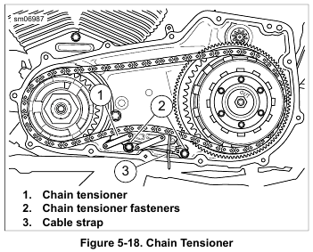
17. See Figure 5-18. Install primary chain tensioner (1) with fasteners (2). Tighten to 21-24 ft-lbs (28.5-32.6 Nm).
Remove cable strap.
18. Set preliminary chain tension:
a. Check tension at the top span while pulling down on chain midway between sprockets. Correct tension is 0.500-0.625 in (13-14 mm
b. If chain is loose, move chain adjuster one notch.
Check tension.
c. Repeat above steps until tension is within specification.
NOTES
• Always install a new gasket between primary cover and housing. Not replacing this gasket may cause primary chaincase leaks.
• Verify that all debris is washed from the inside ribs.
19. Install primary chaincase cover. Fill primary chaincase.
See 5.3 PRIMARY CHAINCASE COVER, Installation.
20. Connect negative battery cable.
Leave a Reply