Author: Sam

  • 2015 Touring – TRANSMISSION ASSEMBLY – DISASSEMBLY

    Shifter Cam/Shifter Forks

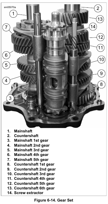
    1. See Figure 6-14. Disassemble bearing housing assembly:
    a. Place bearing housing on end (shafts pointing upward).
    b. Remove shift fork shafts using easy-out screw extractor (14) (non-flute design) or vise grips. Shafts have slight interference fit. Shafts can be reused; do not damage end of shaft.
    c. Mark end of shaft to aid during assembly.

    2. Remove shift forks from dog rings.

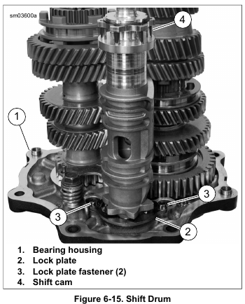
    3. See Figure 6-15. Remove lock plate fasteners (3) from lock plate (2). Discard fasteners.

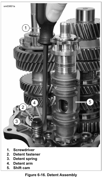
    4. See Figure 6-16. Insert screwdriver and gently pry back detent arm (4) to remove detent spring (3) tension from shift cam (5). Remove shift cam.

    5. If servicing detent assembly, remove detent screw (2), detent arm (4), sleeve and detent spring (3). Discard detent screw.

    NOTE

    Many transmission parts can be installed in either direction.
    To prolong usable life, install used parts in same direction as when removed.

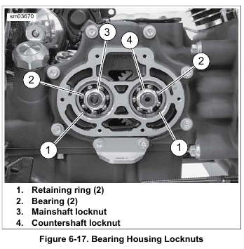
    6. See Figure 6-17. Using dog rings, lock two gears in place.
    Temporarily place transmission assembly into transmission case.

    7. Remove mainshaft and countershaft locknuts.

    8. Remove transmission assembly from transmission case.

    Mainshaft

    NOTE

    The mainshaft 4th gear, 3rd gear, 2nd gear and 1st gear are integral parts of the shaft. Damage to any gear requires mainshaft replacement.

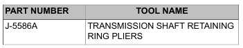
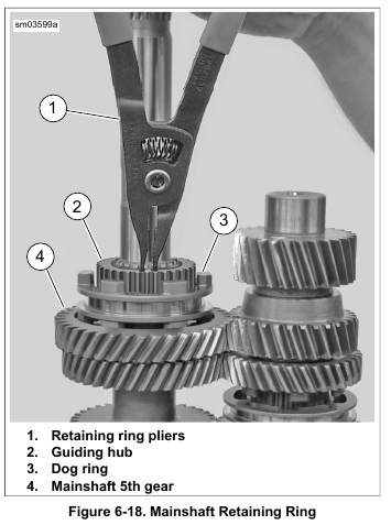
    1. See Figure 6-18. Using TRANSMISSION SHAFT RETAINING RING PLIERS (Part No. J-5586A), remove retaining ring. Remove dog ring (3), guiding hub (2), mainshaft 5th gear (4) and bearing.

    NOTE

    Do not press directly on the end of the mainshaft. Place a spacer such as a washer between the end of the mainshaft and the press ram.

    2. Place transmission assembly in arbor press. Press mainshaft out of bearing housing bearings.

    Countershaft

    NOTES

    • If removing countershaft without removing the mainshaft, hold countershaft 3rd and 4th gear shift dog up while pressing countershaft out of bearing housing bearings.
    • Do not press directly on the end of the countershaft. Place a spacer such as a washer between the end of the countershaft and the press ram.

    1. Press countershaft out of bearing housing bearings.

    2. See 6.8 TRANSMISSION ASSEMBLY for bearing housing bearing replacement.

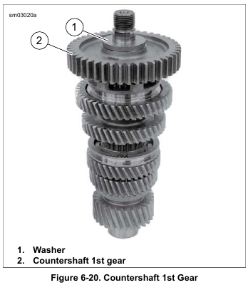
    3. See Figure 6-20. Remove washer (1), countershaft 1st gear (2) and bearing.

    NOTE

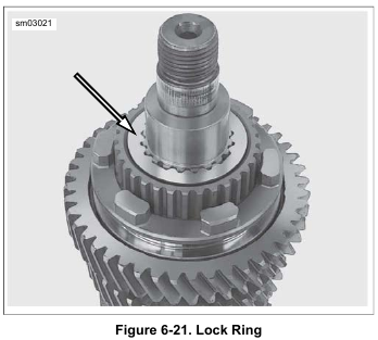
    See Figure 6-21. Note the direction that the 2nd gear locking ring is installed.

    4. Remove countershaft 2nd gear lock ring.

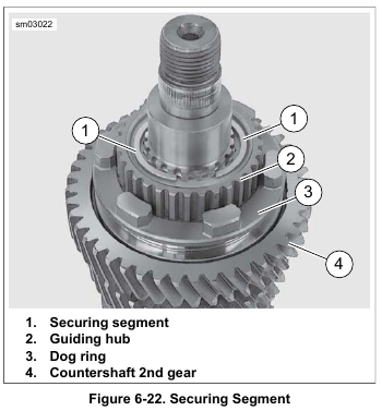
    5. See Figure 6-22. Remove securing segments (1). Remove dog ring (3), guiding hub (2), countershaft 2nd gear (4) and bearing.

    NOTE

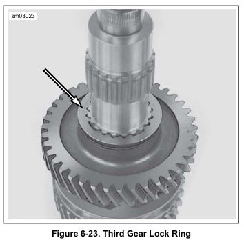
    See Figure 6-23. Note the direction that the 3rd gear locking ring is installed.

    6. Remove countershaft 3rd gear lock ring.

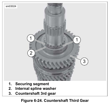
    7. See Figure 6-24. Remove securing segments (1), internal spline washer (2), countershaft 3rd gear (3) and bearing.

    NOTE

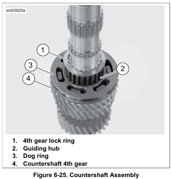
    See Figure 6-25. Note the direction that the 4th gear locking ring is installed.

    8. Remove 4th gear lock ring (1), securing segments, dog ring (3), guiding hub (2) and countershaft 4th gear (4) and bearing.

    NOTE

    The countershaft 5th gear and 6th gear are integral parts of the shaft. Damage to either gear requires countershaft replacement.

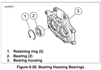
    Removing Bearing Housing Bearings

    NOTE

    Always replace bearing housing bearing if the shaft is pressed out.

    1. See Figure 6-26. Remove the retaining rings (1).

    2. Press the bearings out of the bearing housing.


  • 2015 Touring – TRANSMISSION ASSEMBLY – REMOVAL

    NOTE

    Leave the transmission case in the frame unless the case itself requires replacement. For illustration purposes, some photographs may show the case removed. For information on case removal see 6.10 TRANSMISSION CASE.

    1. Remove exhaust system. See 4.18 EXHAUST SYSTEM.

    2. Relieve drive belt tension. See 1.14 DRIVE BELT AND SPROCKETS.

    3. Remove primary chaincase cover, clutch assembly, primary chain, compensating sprocket assembly and primary chaincase. See 5.5 PRIMARY CHAINCASE HOUSING, Removal.

    4. Remove the transmission mainshaft bearing inner race.
    See 5.5 PRIMARY CHAINCASE HOUSING, Mainshaft Bearing Inner Race.

    5. Remove the clutch release cover. See 6.5 CLUTCH RELEASE COVER: CABLE CLUTCH, Removal and Disassembly.

    6. See Figure 6-10. Remove oil slinger assembly from mainshaft. Insert long rod through mainshaft bore and remove pushrod.

    7. Remove transmission top cover, leaving the cover gasket in place.

    8. See Figure 6-11. Rotate the shifter pawl forward enough to raise the free end and place shifter cam pawl on top cover gasket.

    NOTES

    • Remove and install sprocket nut only while transmission is in vehicle frame. Removing or installing sprocket nut with transmission in transmission stand may cause damage to transmission or stand.
    • Replace the main drive gear bearing and retainer if the main drive gear is removed. The bearing will be damaged during the removal procedure.

    9. If main drive gear is to be removed, see 6.9 MAIN DRIVE GEAR AND BEARING, Removal.

    10. Cover mainshaft clutch hub splines with tape to prevent the splines damaging the main drive gear bearings.

    11. See Figure 6-13. Remove the transmission bearing housing mounting hardware. Remove exhaust bracket, if equipped.

    NOTE

    See Figure 6-12. Never tap on shafts with a hammer to remove transmission assembly. The bearing housing bearings will be damaged. Pry loose using indents at each side of bearing housing.

    12. Pry the bearing housing loose. Remove bearing housing, mainshaft, countershaft and shifter cam from transmission case as an assembly. Discard gasket.


  • 2015 Touring – SECONDARY CLUTCH ACTUATOR – REPLACEMENT

    1. Remove the transmission outer side cover. See 6.6 TRANSMISSION SIDE COVERS: HYDRAULIC CLUTCH.

    2. See Figure 6-8. Loosen clutch fluid line (2) and allow clutch fluid to drain.

    NOTE

    A small amount of transmission lubricant will drain when secondary clutch actuator is removed.

    3. Remove three screws (3) and secondary clutch actuator (4).

    4. Remove and discard O-ring (5) from secondary clutch actuator.

    NOTES

    • The secondary clutch actuator is not serviceable. Replace as needed.
    • Secondary clutch actuator and O-ring must be seated in cover before tightening screws to specification.

    5. Lubricate new O-ring (5) with transmission lubricant prior to installing. Install new O-ring on secondary clutch actuator.

    6. Install three screws (3) attaching secondary clutch actuator (4) to transmission inner side cover. Tighten to 100-120 in-lbs (11.2-13.6 Nm).

    7. Connect fluid line (2). Tighten to 96-144 in-lbs (10.9-16.3 Nm).

    8. Fill and bleed clutch. See 2.27 BLEEDING CLUTCH CONTROL SYSTEM.

    Validate Repair

    After system is bled, inspect connection at secondary clutch actuator for leaks. If fluid is present, perform following procedure:

    1. See Figure 6-8. Verify connection:
    a. Verify that the clutch line flare nut (2) torque is 96-144 in-lbs (10.9-16.3 Nm).
    b. If leak still persists increase torque to 144-200 in-lbs (16.3-22.6 Nm).
    c. If the leak is still present, remove the secondary clutch actuator to inspect the secondary clutch actuator cavity. See service manual for removal instructions.
    d. Remove clutch line and hold actuator with cavity facing up.
    e. Check to see if copper washer is installed or being added for the first time.

    NOTE

    Copper washer can be installed in secondary clutch actuator only once. It is very difficult to remove from the cavity after it has been in service. A clutch line may be installed multiple times on an actuator with a copper washer installed as long as a seal can be achieved.

    2. See Figure 6-9. Hold secondary clutch actuator upright.
    Install copper washer (Part No. 12300027) in the actuator cavity. Allow copper washer to self-center.

    3. Tighten the clutch line flare nut to 96-144 in-lbs (10.9-16.3 Nm).

    4. Install secondary clutch actuator. See service manual.

    5. If leak still persists increase torque to 144-200 in-lbs (16.3-22.6 Nm).

    6. If a leak is still present, replace the secondary clutch actuator.

    7. Verify proper clutch operation.


  • 2015 Touring – TRANSMISSION SIDE COVERS: HYDRAULIC CLUTCH – INSTALLATION

    1. See Figure 6-7. Place a new clutch release gasket (2) on locating dowels and position inner side cover on transmission.

    2. Tighten inner side cover fasteners to 132-156 in-lbs (14.9-17.6 Nm).

    3. If removed, install secondary clutch actuator (3). See 6.7 SECONDARY CLUTCH ACTUATOR.

    4. Install outer transmission side cover. Tighten to 100-120 in-lbs (11.2-13.6 Nm).

    5. Fill transmission lubricant.

    6. Install other components that were removed.


  • 2015 Touring – TRANSMISSION SIDE COVERS: HYDRAULIC CLUTCH – REMOVAL

    1. Remove seat.

    To prevent accidental vehicle start-up, which could cause death or serious injury, disconnect negative (-) battery cable before proceeding. (00048a)

    2. Disconnect negative battery cable.

    3. Remove transmission filler plug/dipstick.

    4. Drain transmission.

    5. Remove components necessary to access side covers.

    6. See Figure 6-7. Remove outer side cover (5).

    7. If necessary, remove secondary clutch actuator (3). See 6.7 SECONDARY CLUTCH ACTUATOR.

    8. Remove inner side cover (1). Discard gasket (2).

    9. Clean and inspect inner side cover. Clean with denatured alcohol only.

    NOTE

    If damaged, replace locating dowels in inner side cover.


  • 2015 Touring – CLUTCH RELEASE COVER: CABLE CLUTCH – ASSEMBLY AND INSTALLATION

    NOTE

    Replace cable fitting O-ring if damaged.

    1. See Figure 6-4. Apply a drop of LOCTITE 243 MEDIUM STRENGTH THREADLOCKER AND SEALANT (blue) to the clutch cable fitting (1). Install in clutch release cover.
    Do not tighten at this time.

    2. See Figure 6-6. Place outer ramp (3) with ball socket side up in clutch release cover. Confirm tab (8) is in clutch release cover slot.

    3. Apply a multi-purpose grease to the balls and outer ramp sockets. Place a ball in each of the outer ramp sockets.

    4. See Figure 6-4. Connect cable end to ramp coupling (3).
    Install coupling on inner ramp (5). Place inner ramp and coupling in position in clutch release cover.

    NOTE

    Center the opening of the retaining ring above the break in the ribbing at bottom of the clutch release cover.

    5. Install retaining ring (4).

    6. Verify that two dowel pins are in place on transmission bearing housing flange. Place a new gasket on dowel pins.

    NOTE

    See Figure 6-3. Clutch release cover screws in positions (1) and (6) are shorter than the others.

    7. See Figure 6-3. Install clutch release cover. Tighten to 132-156 in-lbs (14.9-17.6 Nm) in sequence shown.

    8. Tighten clutch cable fitting to 90-120 in-lbs (10.2-13.6 Nm).

    9. Fill transmission to proper level with fresh transmission fluid. See 1.11 TRANSMISSION LUBRICANT, Changing Transmission Lubricant.

    10. Adjust clutch cable. See 1.12 CLUTCH CABLE: ROAD KING.

    11. Install exhaust system if removed. See 4.18 EXHAUST SYSTEM.

    12. Install main fuse.


  • 2015 Touring – CLUTCH RELEASE COVER: CABLE CLUTCH – CLEANING AND INSPECTION

    1. See Figure 6-6. Wash the ball and ramp mechanism components in cleaning solvent.

    2. Inspect the three balls (2) and ball socket surfaces on ramps (1, 3) for wear, pitting, surface breakdown and other damage. Replace as necessary.

    3. Check fit of the ramp coupling (4) on inner ramp (1).
    Replace both parts if there is excessive wear.

    4. Inspect the retaining ring (6) for damage or distortion.

    5. Check clutch cable end for frayed or worn ends. Replace cable if damaged or worn. Check cable fitting O-ring for damage.

    6. Check the bore in the clutch release cover (5) where the ramps (1, 3) are retained. There should be no wear that would cause the ramps to tilt, causing improper clutch adjustment.


  • 2015 Touring – CLUTCH RELEASE COVER: CABLE CLUTCH – REMOVAL AND DISASSEMBLY

    1. Remove main fuse.

    2. Remove exhaust system if needed. See 4.18 EXHAUST SYSTEM.

    3. Drain transmission. See 1.11 TRANSMISSION LUBRICANT.

    NOTE

    Actuating the clutch hand lever after removing the six screws will help break the cover free.

    4. See Figure 6-3. Remove six screws securing the clutch release cover. Remove the clutch release cover. Discard the gasket.

    5. Add free play to clutch cable. See 1.12 CLUTCH CABLE: ROAD KING.

    6. See Figure 6-4. Remove retaining ring (4). Lift inner ramp (5) and ramp coupling (3) out of clutch release cover.
    Disconnect clutch cable end (2) from the ramp coupling (3).

    7. Remove coupling (3) from inner ramp.

    8. See Figure 6-5. Remove balls (4) and outer ramp (2).

    9. Remove clutch cable fitting from clutch release cover.


  • 2015 Touring – SHIFTER LINKAGE – SHIFTER ROD LEVER, FRONT

    Removal

    1. See Figure 6-2. Remove nut (10) and lockwasher (9) to free linkage.

    2. Mark position of shifter rod lever in relation to shaft.

    3. Remove pinch screw. Remove shifter rod lever.

    Installation

    1. Install shifter rod lever. Align to marks made during removal.

    2. Install pinch screw. Tighten to 90-110 in-lbs (10.2-12.4 Nm).

    3. Install flat washer on shift linkage stud.

    4. Secure linkage to shifter rod lever with flat washer, lockwasher and nut. Tighten to 70-90 in-lbs (7.9-10.2 Nm).

    5. Verify shift lever operation.


  • 2015 Touring – SHIFTER LINKAGE – HEEL-TOE SHIFT LEVERS

    Removal

    1. See Figure 6-2. Mark position of levers in relation to shaft.

    2. Remove pinch screws securing heel and toe shift levers.

    3. Remove levers from shaft.

    4. Remove rubber spacer.

    Repair

    1. Remove screw securing rubber peg to lever. Separate screw from peg.

    2. Assemble peg to lever with screw. Tighten to 96-144 in-lbs (10.9-16.3 Nm).

    Installation

    1. Install rubber spacer.

    NOTE

    Shift lever peg height is a customer preference. During installation, check operation of both shift levers. To achieve proper gear engagement and to avoid damage to transmission, the pegs must not contact the footboard when shifting.

    2. Install heel and toe levers. Align to marks made during removal.

    3. Install pinch screws. Tighten to 18-22 ft-lbs (24.4-29.8 Nm).

    4. Verify shift lever operation.