Author: Sam

  • 2015 Touring – STARTER – REMOVAL

    1. Remove seat. See 2.30 SEAT.

    Disconnect negative (-) battery cable first. If positive (+) cable should contact ground with negative (-) cable connected, the resulting sparks can cause a battery explosion, which could result in death or serious injury. (00049a)

    2. Remove negative cable from battery.

    NOTE

    The battery positive cable and power wire for the main fuse are crimped together at the starter ring terminal.

    3. Remove battery positive and main fuse power cable ring terminal from starter solenoid stud.

    4. Remove starter solenoid connector [128] at front of starter.

    5. Remove engine oil filler cap/dipstick. Cover fill spout with clean shop cloth to keep out dirt and debris.

    6. Remove starter mounting screws.

    7. Remove starter. Avoid losing the ring dowels.


  • 2015 Touring – STARTER – GENERAL

    The starter assembly includes a field coil, solenoid and drive assembly.

    NOTES

    • For troubleshooting and diagnostic information see the electrical diagnostic manual.
    • Use touch-up paint as necessary prior to installation. Paint flaking does not require starter replacement.

  • 2015 Touring – IGNITION COIL – INSTALLATION

    1. See Figure 7-9. While holding ground terminal wires out of the way, place ignition coil (1) into position.

    2. Install battery hold-down bracket (3) and screws (2).
    Tighten to 32-40 in-lbs (3.6-4.5 Nm).

    3. Tighten ground terminal nut (4) to 50-90 in-lbs (5.7-10.2 Nm).

    4. See Figure 7-8. Install ignition coil connector.

    NOTE

    Frame is stamped with “F” and “R” near the coil towers to identify correct cable attachment.

    5. Connect spark plug wires (1, 2) to ignition coil towers.

    6. Install battery. See 1.22 BATTERY MAINTENANCE.


  • 2015 Touring – IGNITION COIL – REMOVAL

    1. Remove battery. See 1.22 BATTERY MAINTENANCE.

    2. See Figure 7-8. Remove spark plug wires (1, 2) from ignition coil towers.

    3. Remove ignition coil connector.

    4. See Figure 7-9. Remove screws (2) and battery hold-down bracket (3).

    5. Loosen ground terminal nut (4). While holding ground terminal wires out of the way, remove ignition coil (1).

  • 2015 Touring – IGNITION COIL – SPARK PLUG CABLE INSPECTION

    1. Inspect spark plug cables. Replace if necessary.
    a. Check for cracks or loose terminals.
    b. Check for loose fit on ignition coil and spark plugs.

    2. Check cable boots/caps for cracks or tears. Replace boots/caps that are worn or damaged.

    3. See Figure 7-7. Check spark plug cable resistance with an ohmmeter. Replace cables not meeting resistance specifications. Refer to Table 7-5.

  • 2015 Touring – ELECTRICAL CADDIES – BATTERY TRAY

    Removal

    1. Remove seat. See 2.30 SEAT.

    2. Remove battery. See 1.22 BATTERY MAINTENANCE.

    3. Remove screws securing left side caddy. Pull caddy away from frame while pulling rear fender lights harness out through battery tray.

    4. Remove ignition coil screws and battery hold-down bracket. See 7.7 IGNITION COIL.

    5. Remove screw securing right side caddy, if equipped.

    6. Models without right side caddy: Release O2 sensor connectors from retaining devices.

    7. Models without active exhaust: Remove actuator connector from cavity in battery tray.

    8. Remove four screws securing battery tray to frame.

    9. Models with right side caddy: Disengage latch on bottom of caddy. Release caddy from dovetails while lowering battery tray into frame.

    10. Roll front of battery tray up and out of frame.

    Installation

    1. Roll rear of battery tray down into frame.

    2. Models with right side caddy: Engage right side caddy onto dovetails while lifting battery tray up into position. Verify latch on bottom of caddy is engaged.

    3. Install screw to retain caddy to battery tray. Tighten to 36-40 in-lbs (4.1-4.5 Nm).

    4. Install four screws securing battery tray to frame. Tighten to 132-156 in-lbs (14.9-17.6 Nm).

    5. Models without active exhaust: Install actuator connector to cavity in battery tray.

    6. Models without right side caddy: Secure O2 sensor connectors to retaining devices.

    7. Install battery hold-down bracket and screws to secure ignition coil. Tighten to 32-40 in-lbs (3.6-4.5 Nm).

    8. Route rear fender lights connector through opening in battery tray and up through opening in frame. Secure left side caddy with screws. Tighten to 72-96 in-lbs (8.1-10.9 Nm).

    9. Mate rear fender lights connector. Secure to retaining device.

    10. Secure main harness to left top frame with two cable straps.

    11. Install battery and top caddy. See 1.22 BATTERY MAINTENANCE.

    12. Install seat. See 2.30 SEAT.

    13. Install side covers and saddlebags.

  • 2015 Touring – ELECTRICAL CADDIES – RIGHT SIDE CADDY

    Removal

    1. Remove right saddlebag.

    2. Remove right side cover.

    3. Remove battery. See 1.22 BATTERY MAINTENANCE.

    4. Remove O2 sensor connector anchors.

    5. Remove wheel speed sensor connector anchor, if equipped.

    6. Remove ignition coil screws and battery hold-down bracket.

    7. See Figure 7-6. Remove screw (1) securing right side caddy to battery tray.

    8. Remove four screws securing battery tray to frame.

    9. Disengage latch on bottom of caddy. Release caddy from dovetails while lowering battery tray into frame.

    NOTE

    Stud on bottom of ABS module is a tight fit in grommet. Considerable effort may be needed to remove module.

    10. Loosen nuts securing ABS module assembly (3), if equipped. Remove ABS module from caddy.

    11. Remove active exhaust actuator (2), if equipped. Disconnect cable from actuator. See 4.19 ACTIVE EXHAUST: HDI.

    12. Remove caddy.

    Installation

    1. Install active exhaust actuator, if equipped. See 4.19 ACTIVE EXHAUST: HDI.

    2. Install ABS module to caddy. Apply glass cleaner to grommets to aid installation. Tighten to 53-88 in-lbs (6-10 Nm).

    3. Engage right side caddy onto dovetails while lifting battery tray up into position. Verify latch on bottom of caddy is engaged.

    4. See Figure 7-6. Install screw (1). Tighten to 36-40 in-lbs (4.1-4.5 Nm).

    5. Install four screws securing battery tray to frame. Tighten to 132-156 in-lbs (14.9-17.6 Nm).

    6. Install battery hold-down bracket and screws to secure ignition coil. Tighten to 32-40 in-lbs (3.6-4.5 Nm).

    7. Secure O2 sensor connector anchors. Locate the gray connector in the outboard position.

    8. Secure the wheel speed sensor connector anchor, if equipped.

    9. Install battery and top caddy. See 1.22 BATTERY MAINTENANCE.

    10. Install seat. See 2.30 SEAT.

    11. Install side cover and saddlebag.


  • 2015 Touring – ELECTRICAL CADDIES – LEFT SIDE CADDY

    Removal

    1. Remove left saddlebag. See 2.31 SADDLEBAGS.

    2. Remove left side cover.

    3. Remove seat. See 2.30 SEAT.

    4. Siren Equipped Models: With security fob present, turn ignition switch ON.

    5. Remove main fuse.

    6. Disconnect rear fender lights harness connector. Remove connector from retaining device.

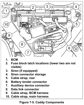
    7. See Figure 7-5. Disconnect and remove BCM (1). See 7.5 BODY CONTROL MODULE (BCM).

    8. Disconnect and remove siren (3), if equipped. If not equipped, remove connector from storage location (4) on caddy.

    9. Release data link connector (8), auxiliary device connector (7) and battery tender connector (6) from caddy.

    10. Remove fuse block cover.

    11. Remove two screws securing caddy.

    12. Remove cable straps (5, 9, 10).

    13. Pull harnesses back through openings in caddy.

    14. Use a thin tool to release four latches (2) securing fuse block. Push fuse block back through opening in caddy.

    15. From back side of caddy, squeeze tabs of main fuse holder and pull away from caddy.

    Installation

    1. See Figure 7-5. Route harnesses through openings.

    2. Loosely install a new cable strap on the BCM harness.

    3. Loosely secure main harness to anchor on back side of caddy with cable strap (10).

    4. Install main fuse holder into caddy. Confirm the latches on the fuse holder are secured to the caddy.

    5. Insert fuse block from back side of caddy. Confirm the latches (2) are secured to the fuse block.

    6. Loosely secure BCM harness to tab with previously installed cable strap (9).

    7. Loosely secure harnesses to tab at rear opening with a cable strap (5).

    NOTE

    Tighten cable straps only enough to secure harnesses but still allow movement.

    8. Tighten the main harness, BCM harness then rear harness cable straps until snug.

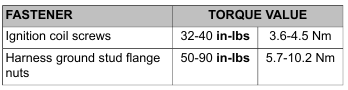
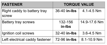
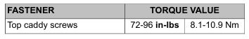
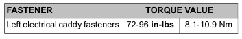
    9. Route rear fender lights connector through opening in battery tray and up through opening in frame. Secure caddy with two screws. Tighten to 72-96 in-lbs (8.1-10.9 Nm).

    10. Secure auxiliary device connector (7), data link connector (8), and battery tender connector (6) to caddy.

    11. Install fuse block cover.

    12. Install siren (3) and attach electrical connector, if equipped.
    If not equipped, attach connector to storage location (4).

    13. Connect and install BCM (1). See 7.5 BODY CONTROL MODULE (BCM).

    14. Connect rear fender lights harness connector. Secure to retaining device.

    15. Install main fuse.

    16. Install seat. See 2.30 SEAT.

    17. Install left side cover.

    18. Install left saddlebag. See 2.31 SADDLEBAGS.

    Be sure that all lights and switches operate properly before operating motorcycle. Low visibility of rider can result in death or serious injury. (00316a)


  • 2015 Touring – ELECTRICAL CADDIES – TOP CADDY

    Removal

    1. Remove seat. See 2.30 SEAT.

    2. See Figure 7-4. Remove HFSM antenna (6), if present.

    3. Lift up on ECM (3) until free of caddy.

    4. Remove connectors (4, 5) from retaining devices.

    5. Remove screws (2).

    6. Lift caddy and slide purge valve solenoid (7) from caddy, if present. Remove caddy.

    Installation

    1. See Figure 7-4. Install purge valve solenoid (7) on caddy (1). Place caddy into position over battery.

    2. Install screws (2). Tighten to 72-96 in-lbs (8.1-10.9 Nm).

    3. Install ECM (3).

    4. Install HFSM antenna (6) onto caddy, if present.

    5. Secure connectors (4, 5) to retaining devices.

    6. Install seat. See 2.30 SEAT.


  • 2015 Touring – ELECTRICAL CADDIES – FAIRING AND STEERING HEAD CADDIES

    For service of the fairing harness caddy, see 7.36 FAIRING HARNESS.

    For service of the steering head caddies, see 7.35 MAIN WIRING HARNESS.