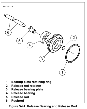
1. See Figure 5-41. Pressing on the outer race, press a new release bearing (4) into bearing plate (3).
2. Assemble release rod (5) to bearing.
3. Install new retainer (2).
4. Install pushrod if removed.
5. Seat the bearing plate in the clutch. Install bearing plate retaining ring (1).
NOTE
Before installing the clutch inspection cover, check release plate movement.
Measure Release Plate Movement
1. Attach a dial indicator to measure pushrod axial movement.
Insufficient clutch-release plate movement can lead to difficulty or inability to shift, causing loss of control, which could result in death or serious injury. (00345a)
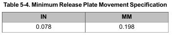
2. Actuate the clutch lever to measure the axial movement of the pushrod and the clutch-release plate assembly. The minimum axial movement must be as specified. Refer to Table 5-4.
NOTE
Proper bleeding of the system will typically yield plate movement greater than specification. If clutch release plate movement is less than specification, bleed system and measure plate movement again.
Install Clutch Inspection Cover
1. Thoroughly clean all gasket material from clutch inspection cover and mating surface on primary cover.
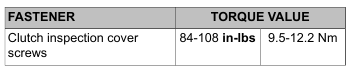
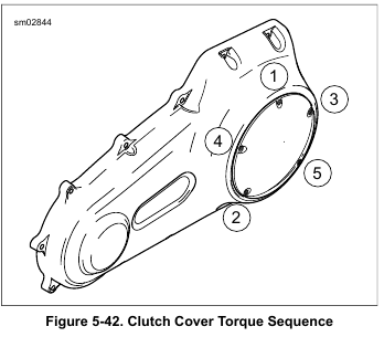
2. See Figure 5-42. Install clutch inspection cover with new gasket. Make sure the correct side of the gasket faces the clutch inspection cover. In star pattern, tighten screws to 84-108 in-lbs (9.5-12.2 Nm).
3. Connect negative battery cable to battery.
After installing seat, pull upward on seat to be sure it is locked in position. While riding, a loose seat can shift causing loss of control, which could result in death or serious injury. (00070b)
4. Install seat.
Leave a Reply