1. Slide approximately 6.0 in. (152 mm) of plastic tubing, rubber hose or conduit over each cylinder stud, if removed. Use material with I.D. of 0.5 in. (12.7 mm) to protect cylinder studs and piston from damage.
2. Apply SCREAMIN’ EAGLE ASSEMBLY LUBE to piston pin, piston bosses and upper connecting rod bore.
3. Remove water pipe insulation from connecting rod shank.
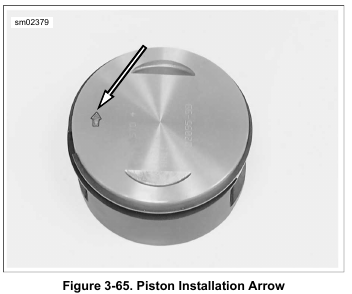
4. See Figure 3-65. Place piston over rod end so that the arrow stamped at the top of the piston points toward the front of the engine.
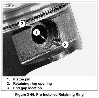
5. See Figure 3-66. Insert piston pin (1) through pin bore and upper connecting rod bore. Push pin until it contacts retaining ring installed in opposite pin boss. Verify that end gap (3) for retaining ring is 180 degrees from opening (2).
6. Place clean shop towels over the cylinder and lifter bores to prevent the piston pin retaining ring from falling into the crankcase. Verify that the retaining ring groove is clean and free of dirt and grime.
NOTE
Do not reuse piston pin retaining rings. They could weaken during removal causing them to break or dislodge during engine operation. This condition will result in engine damage.
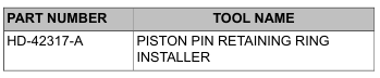
7. Install new piston pin retaining ring with the PISTON PIN RETAINING RING INSTALLER (Part No. HD-42317-A).
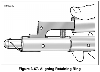
a. See Figure 3-67. Slide retaining ring down nose of tool until it contacts claw. Lightly squeeze handles of tool to capture retaining ring in claw.
b. Releasing pressure on handles, rotate retaining ring so that the end gap is centered at top of tool and then recapture in claw.
c. Tilt the retaining ring forward until the end gap contacts nose of tool.
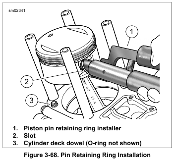
d. See Figure 3-68. Insert the tool (1) into the piston pin bore until claw is aligned with slot (2) in piston.
e. Firmly push the tool into the piston pin bore until it bottoms. Release handles and remove tool.
f. Inspect the retaining ring to verify that it is fully seated in the groove.
Leave a Reply