NOTES
• “Front” or “Rear” is cast into the top of the cylinder head to verify proper installation. The indent in the cooling fins always faces the right side of the engine.
• Lower the cylinder head at an angle that closely approximates the angle of the crankcase to avoid damage to machined surfaces or the dowel pins.
• Thoroughly clean and lubricate the threads of the cylinder headbolts before installation. Friction caused by dirt and grime results in a false torque indication.
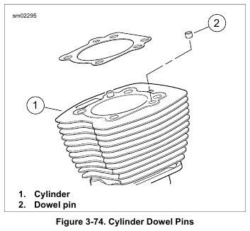
1. See Figure 3-74. With the part number facing up, place the head gasket over the two dowel pins in the upper flange of the cylinder.
2. Slide cylinder head squarely over the two cylinder flange dowel pins.
3. Lightly coat the threads and bottom face of the cylinder headbolts in clean engine oil. Wipe off any excess oil.
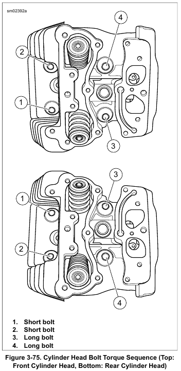
4. See Figure 3-75. Loosely install the cylinder headbolts.
Place two short bolts on the left side of the engine and two long bolts on the right.
NOTE
Improperly tightened cylinder headbolts may result in gasket leaks, stud failure or distortion of the cylinder and/or cylinder head.
5. Tighten the cylinder headbolts:
a. See Figure 3-75. Following sequence shown, turn each cylinder headbolt until finger-tight.
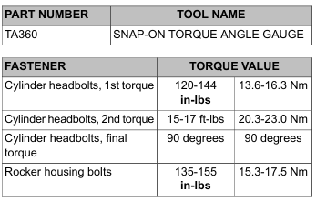
b. Following the same sequence, tighten the cylinder headbolts to 120-144 in-lbs (13.6-16.3 Nm).
c. Continuing the same sequence, tighten each bolt to 15-17 ft-lbs (20.3-23.0 Nm).
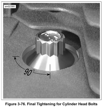
6. See Figure 3-76. Final-tighten each bolt an additional 90 degrees (90 degrees) in the same sequence. For best results, use SNAP-ON TORQUE ANGLE GAUGE (Part No. TA360).
a. If using a grease pencil, mark a straight line on the cylinder headbolt continuing the line over onto the cylinder head.
b. Use the marks as a guide to achieve the 90 degrees.
NOTE
The tips of ACR solenoids for Twin-Cooled engines are approximately 0.500 in (13 mm) longer than those for air-cooled engines. Twin-Cooled ACR’s will contact the pistons of an air cooled engine.
7. 103 and larger engines: Install the ACR. See 7.19 AUTOMATIC COMPRESSION RELEASE (ACR).
NOTES
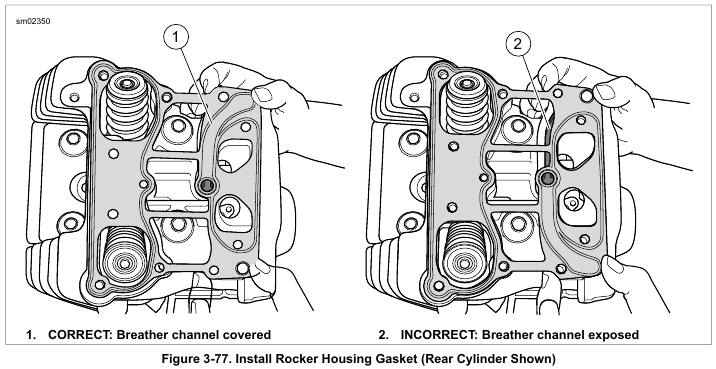
• The rocker housing gasket can be installed upside down resulting in an open breather channel. This causes a major oil leak when the vehicle is started, possibly resulting in engine and/or property damage.
• On front cylinder head, install side of gasket marked “front” facing up. On rear cylinder head, install side of gasket marked “rear” facing up.
8. See Figure 3-77. Install a new rocker housing gasket on the cylinder head. Verify that the rocker housing gasket covers the breather channel.
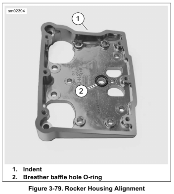
9. See Figure 3-79. Install rocker housing.
a. With the indent (1) facing forward, place the rocker housing into position aligning the holes in the housing with those in the gasket.
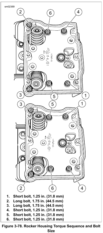
b. See Figure 3-78. Apply a drop of LOCTITE 243 MEDIUM STRENGTH THREADLOCKER AND SEALANT (blue) to threads of six rocker housing bolts.
c. Loosely install the rocker housing bolts.
d. Place two long bolts on the left side of the engine and four intermediate bolts in the interior.
e. Tighten the bolts in the sequence shown to 135-155 in-lbs (15.3-17.5 Nm).
NOTES
• If the engine was left in the chassis for service, final tighten the rear left rocker housing bolt (rear cylinder) using a torque wrench with a 1/4 in. drive.
• Since many O-rings are similar in size and appearance, always use new O-rings, keeping them packaged until use to avoid confusion. Use of the wrong O-ring will result in either oil leakage or low oil pressure. Keep them packaged until use to avoid confusion.
10. See Figure 3-79. Apply a very thin film of clean engine oil to new baffle hole O-ring (2). Install new O-ring in groove around breather baffle hole in rocker housing.
NOTE
Do not confuse breather baffle hole O-ring (Part No. 11270, large inner diameter) with the top pushrod O-ring (Part No. 11293, small inner diameter).
Leave a Reply