1. Using dye penetrant, inspect the cylinder for cracks. If no cracks are found, thoroughly wash cylinder to remove traces of dye.
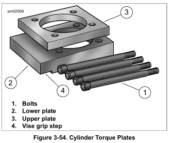
2. See Figure 3-54. Check the machined surfaces for flatness using a feeler gauge and CYLINDER TORQUE PLATES (Part No. HD-42324-A):
a. Lay gasket side of the upper torque plate (3) flat against the head gasket surface of the cylinder.
b. As a preliminary check, see if the plate rocks from side to side. A cylinder on which the plate rocks is immediately suspect.
c. Insert a feeler gauge between the plate and cylinder at various locations.
d. The head gasket surface must be flat within 0.006 in. (0.15 mm).
e. Lay the seal side of the lower torque plate (2) flat against the O-ring seal surface and check flatness using a feeler gauge.
f. The O-ring seal surface must be flat within 0.004 in. (0.102 mm).
g. Replace the cylinder (and piston) if either surface exceeds specification.
NOTE
Failure to use cylinder torque plates can produce measurements that vary by as much as 0.001 in. (0.025 mm). This may result in the use of parts that are unsuitable for service.
3. Install CYLINDER TORQUE PLATES (Part No. HD-42324-A) :
a. Remove O-ring seal from cylinder sleeve, if installed.
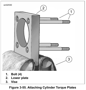
b. See Figure 3-55. Clamp the stepped side of the lower plate in a vise with soft jaws.
c. Lightly oil threads and shoulders of four bolts (1) with clean engine oil and slide through holes of lower plate (2).
d. Slide cylinder onto bolts with the indent in the cooling fins facing upward.
e. Place a used head gasket on cylinder and install upper plate with blind holes aligned with dowel pins in cylinder. Secure with bolts (1).
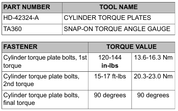
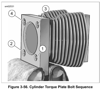
f. See Figure 3-56. Tighten the bolts to 120-144 in-lbs (13.6-16.3 Nm) in the sequence shown.
g. Following the same sequence, tighten each bolt to 15-17 ft-lbs (20.3-23.0 Nm).
h. Final-tighten each bolt an additional 90 degrees (90 degrees) in the same sequence.
NOTE
For best results use SNAP-ON TORQUE ANGLE GAUGE (Part No. TA360). If the tool is not available, mark a straight line on each bolt head continuing the line onto the lower plate.
NOTE
Maximum cylinder wear occurs at the top of top ring travel. Minimum wear occurs below ring travel. Always take measurements in both areas.
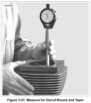
4. See Figure 3-57. Using an inside micrometer or dial bore gauge, check cylinder bore for out-of round and taper:
a. At the top of the piston ring travel zone, measure the cylinder diameter at two locations; parallel and perpendicular to the crankshaft. Record the readings.
b. Repeat the two measurements at the center of the piston ring travel zone and again at the bottom of the bore at a point below the piston ring travel zone.
c. See 3.3 SERVICE WEAR LIMITS. If the out-of-round or taper measurements are not within specification, the cylinder must be rebored and/or honed to accept the next standard oversize piston. See 3.23 CYLINDER, Boring and Honing Cylinder.
d. If cylinders are not scuffed or scored and are not worn beyond the service limits, see 3.23 CYLINDER, Deglazing Cylinder.
Leave a Reply