Removal
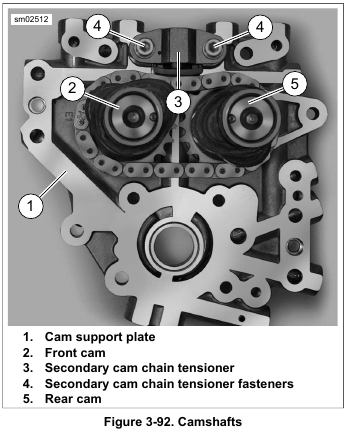
1. See Figure 3-92. Remove screws (4) and remove secondary cam chain tensioner (3).
2. Remove retaining ring securing front camshaft. Discard retaining ring.
3. Remove spacer from front camshaft. Do not mix front and rear camshaft spacers. Front spacer is 0.100 in. (2.54 mm) thick.
4. Using a colored marker, mark one of the links of the secondary cam chain. Maintaining the original direction of rotation during assembly may prolong service life.
5. Slide camshafts and secondary cam chain out of cam support plate.
6. Remove secondary cam chain from cam sprockets.
Installation
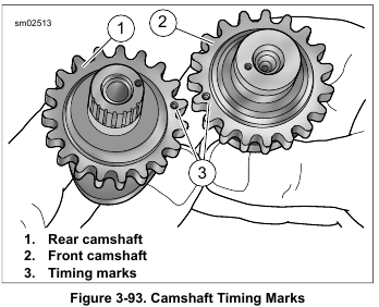
1. See Figure 3-93. Align timing marks on teeth of secondary cam sprockets.
NOTE
Do not mix camshafts during installation. The rear camshaft, identified by the splined shaft, must go into the hole at the rear of the cam support plate.
2. Place secondary cam chain around sprockets of both front and rear camshafts while keeping timing marks (3) in alignment. To maintain original direction of rotation, verify mark placed on chain link during disassembly is visible during installation.
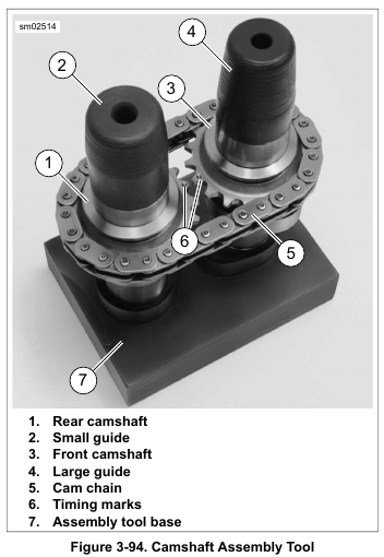
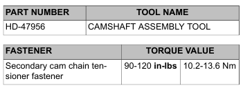
3. See Figure 3-94. Obtain CAMSHAFT ASSEMBLY TOOL (Part No. HD-47956). Place crankcase side of camshaft/cam chain assembly into assembly tool base (7) while maintaining cam timing mark (6) alignment.
4. Place small guide (2) on rear camshaft (1). Place large guide (4) on front camshaft (3).
5. Lubricate support plate camshaft cavities with SCREAMIN’ EAGLE ASSEMBLY LUBE.
6. Install cam support plate over guides.
7. Remove guides and base.
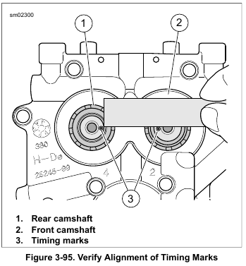
8. See Figure 3-95. Using a straightedge, verify that the timing marks are in alignment. If they are not, then the camshafts must be removed, realigned and reinstalled.
9. Install 0.100 in. (2.54 mm) thick front camshaft spacer over end of front camshaft.
10. With the sharp edge out, install new retaining ring in groove at end of front camshaft.
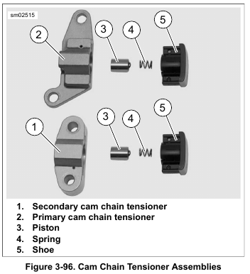
11. Inspect primary and secondary cam chain tensioners.
a. Inspect tensioners for wear. Replace tensioners if damaged or if chain contact portion of shoe material is less than 0.060 in. (1.52 mm) thick.
b. See Figure 3-96. Be sure primary and secondary cam chain tensioners are assembled as shown. If assembled incorrectly, tensioners will not function
properly.
12. Install secondary cam chain tensioner and fasteners.
Tighten to 90-120 in-lbs (10.2-13.6 Nm).
Leave a Reply