Removal
NOTES
• Always keep the wheel speed sensor (WSS) and ABS encoder bearing away from magnetic fields. Items such as magnetic parts trays, magnetic base dial indicators, alternator rotors, etc. will damage sensor.
• Never pull WSS cable taut or use to retain wheel, axle or other components.
1. Remove right saddlebag. See 2.31 SADDLEBAGS.
2. Remove right side cover.
3. Release rear WSS connector from anchor on right side battery tray. Disconnect connector.
4. Rear WSS cable and rear brake hose are secured to the rear fork with two cable retainers. The sensor cable is additionally secured to the brake hose with a conduit clip.
Free rear WSS cable from all three.
5. Retract axle until rear WSS is free. See 2.5 REAR WHEEL.
NOTE
The WSS works in conjunction with the ABS encoder bearing installed in the wheel hub. If necessary, see 2.10 SEALED WHEEL BEARINGS for bearing removal and installation instructions.
Installation
NOTE
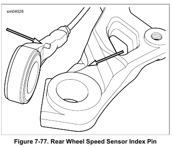
Install WSS with index pin on the outboard side.
1. See Figure 7-77. Hold new rear WSS in place with index pin outboard toward rear fork, and push axle through sensor, caliper bracket and right side of rear fork.
2. Secure rear wheel. See 2.5 REAR WHEEL. Rotate rear WSS until index pin makes contact with caliper bracket at point shown in Figure 7-77.
3. Route rear WSS cable forward along top of rear fork.
4. Capture rear WSS cable and brake hose in rear cable clips on top of rear fork. Secure cable to brake hose with conduit clip placed 1.25 in. (31.8 mm) ahead of the rear brake hose crimp.
5. Route cable to outboard right side of battery caddy. Connect pin and socket housings. Secure to anchor.
6. Install right side cover.
7. Install right saddlebag. See 2.31 SADDLEBAGS.
Leave a Reply