NOTE
Install sprocket nut only while transmission is installed in frame. Failure to do so will result in damage to transmission and/or transmission stand.
1. Place transmission sprocket in position. Install the belt on the sprocket as the sprocket is installed.
2. If reusing the sprocket nut, apply LOCTITE 271 HIGH STRENGTH THREADLOCKER (red) to the threads of the sprocket nut.
NOTES
• Never get oil on the threads of the sprocket nut or the integrity of the lock patch may be compromised.
• The transmission sprocket nut has right-hand threads.
Turn the nut clockwise to install.
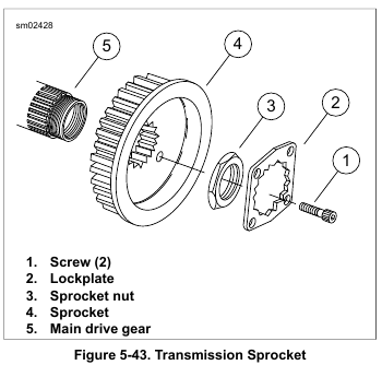
3. See Figure 5-43. Apply a thin film of clean engine oil on the inner face of the sprocket nut (3) and the outer face of the sprocket (4) where the two parts contact each other.
Install the sprocket nut finger-tight.
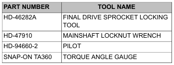
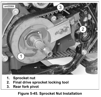
4. See Figure 5-45. Lock transmission sprocket with the FINAL DRIVE SPROCKET LOCKING TOOL (Part No. HD-46282A) (2). The locking tool must rest against the rear fork pivot (3).
5. Install PILOT (Part No. HD-94660-2) on mainshaft.
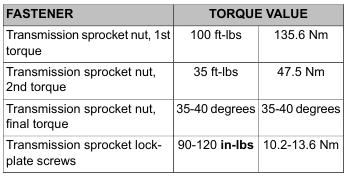
6. Using MAINSHAFT LOCKNUT WRENCH (Part No. HD-47910), tighten sprocket nut to 100 ft-lbs (135.6 Nm) initial torque.
7. Loosen sprocket nut one full turn.
8. Tighten to 35 ft-lbs (47.5 Nm ).
NOTE
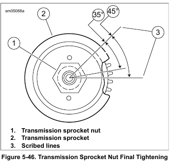
See Figure 5-46. To determine proper angles during final tightening, scribe lines (3) or use TORQUE ANGLE GAUGE (Part No. SNAP-ON TA360) after the 35 ft-lbs (47.5 Nm) torque is applied.
9. Continue an additional 35-40 degrees (35-40 degrees).
NOTE
The lockplate has four screw holes and can be installed either side out. If the screw holes cannot be properly aligned, tighten the nut slightly to align. Do not exceed 45 degrees. Never LOOSEN nut to align the screw holes.
10. Install lockplate over transmission sprocket nut with two lockplate holes aligned with tapped holes in sprocket.
NOTES
• New screws have lock patches.
• Screws can be reused up to three times if LOCTITE 271 HIGH STRENGTH THREADLOCKER (red) is applied before installation.
• Always install BOTH screws.
11. See Figure 5-43. Install two screws (1) to secure lockplate (2). Tighten to 90-120 in-lbs (10.2-13.6 Nm).
12. Install primary chain assembly. See 5.4 DRIVE COMPONENTS.
NOTE
Always install a new gasket between primary cover and housing. Not replacing this gasket may cause primary chaincase leaks.
13. Install primary chaincase cover. Fill primary chaincase.
See 5.3 PRIMARY CHAINCASE COVER.
14. Verify pivot shaft torque. See 2.22 REAR FORK.
15. Adjust drive belt deflection. See 1.14 DRIVE BELT AND SPROCKETS.
Leave a Reply